
The main electrical circuits of this vehicle are protected by fuses. High-current consumers are connected via relays. Most protective elements are located in the passenger compartment fuse box.
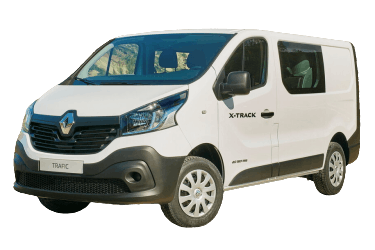
The diagram information applies to third-generation Renault Trafic (chassis codes FG, JG, EG; X82 platform) models produced from 2014 to 2019.
In the Passenger Compartment
This area houses two distribution boxes responsible for protecting the vehicle's electrical circuits.
Fuse Box

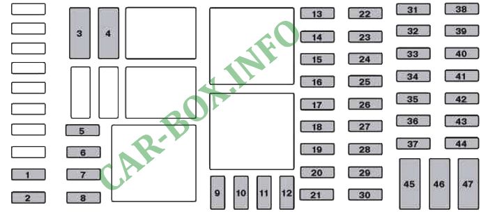
The fuse box is located at the bottom of the dashboard on the driver's side, behind the lower glove compartment.
| Diagram | |
|---|---|
|
|
| No. | Description |
| 1 | Main battery circuit (keyless entry system) |
| 2 | Battery surge protection (keyless entry system) |
| 3 | Heating and ventilation system |
| 4 | Bodybuilder option / Adaptation |
| 5 | Bodybuilder option / Adaptation |
| 6 | Heating and ventilation system |
| 7 | Auxiliary heater, ventilation, and air conditioning (A/C) |
| 8 | Auxiliary heating and ventilation system |
| 9 | Power exterior mirrors |
| 10 | Heated exterior mirrors |
| 11 | Radio, multimedia, exterior mirrors, OBD-II diagnostic socket |
| 12 | Multimedia system, trailer tow hitch |
| 13 | Interior lighting, battery saver system |
| 14 | Fuel injection system, tire pressure monitoring system (TPMS), keyless entry system |
| 15 | Hazard lights, turn signals |
| 16 | Central locking |
| 17 | Left high-beam headlight, right low-beam headlight, tail lights, left daytime running light |
| 18 | Front fog lights, rear fog lights, license plate lights |
| 19 | Horn, warning chime, exterior lighting, wiper/washer system |
| 20 | Instrument cluster |
| 21 | Lighting switch |
| 22 | Rear window wiper, windshield washer pump, horn |
| 23 | ARS (Stop/Start) main battery |
| 24 | Reverse lights |
| 25 | Brake light switch |
| 26 | Fuel injection system, starter motor |
| 27 | Airbags, electronic steering column lock |
| 28 | Passenger power window motor |
| 29 | Power steering |
| 30 | Brake lights |
| 31 | Battery surge protection (keyless entry system) |
| 32 | Service display |
| 33 | Cigarette lighter Trafic 3 (X83), 12V power outlet |
| 34 | Right high-beam headlight, left low-beam headlight, side marker lights, right daytime running light |
| 35 | Brake lights, ABS, engine immobilizer |
| 36 | Interior lighting, air conditioning |
| 37 | Engine start (keyless entry system) |
| 38 | Rear window wiper |
| 39 | Warning buzzer |
| 40 | 12V power outlet in luggage compartment |
| 41 | Driver power window motor |
| 42 | Rear 12V power outlet |
| 43 | Starter circuit, body control module (BCM) |
| 44 | Heated seats |
| 45 | Heater, air conditioner |
| 46 | Windshield wipers |
| 47 | Tachograph |
Relay assignment in the passenger compartment box.
| Diagram | ||
|---|---|---|

|
||
| No. | Description | Amps |
| RH3 | Windshield wiper relay | 40 |
| RH4 | High-speed windshield wiper relay | 40 |
| RH5 | Ignition-switched (+15) supply, rear heating and air conditioning relay | 40 |
| RH6 | Heater core auxiliary water pump relay | 20 |
| RH7 | Driver door power lock relay (SDO) | 20 |
| RH8 | Power distribution relay No. 1 | 70 |
| RH9 | Power distribution relay No. 2 | 40 |
| RH12 | Heated exterior mirrors and heated rear window relay | 40 |
| RH13 | Rear window wiper relay | 30 |
Relay Box
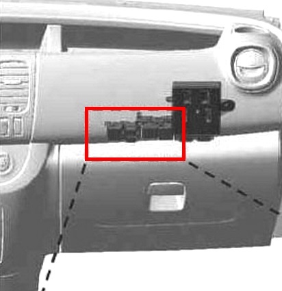
Located behind the dashboard (near the glove box).
| Diagram | ||
|---|---|---|

|
||
| No. | Description | Amps |
| RH11 | Power window relay | 20 |
| RH14 | Central door lock relay | 20 |
| RH15 | Power window relay | 20 |
| RH16 | Ignition-switched (+15) power relay No. 2 (vehicles with hands-free card) | 40 |
| RH17 | Engine running (+15) supply relay | 40 |
In the Engine Compartment
The engine compartment houses two fuse boxes responsible for protecting the vehicle's electrical circuits.
Power Fuse Links
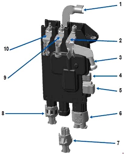
The high-current fuse block is located on the positive battery terminal.

Illustration shown for reference.
| Diagram | ||
|---|---|---|
|
||
| No. | Description | Amps |
| 1 | Battery protection power supply | - |
| 2 | Alternator | 300 |
| 3 | Starter motor | 300 |
| 4 | Mini fuse with cover (Stop/Start system) | 5 |
| 5 | Stop/Start system | 5 |
| 6 | Passenger compartment wiring 50A (bodybuilder option / trailer hitch) | 50 |
| 7 | Reserved for aftermarket bodybuilders | - |
| 8 | Engine Control Unit (ECU) | 35 |
| 9 | Engine junction block | - |
| 10 | Power steering | 120 |
Fuse Box

Located adjacent to the battery.
| Diagram | ||
|---|---|---|
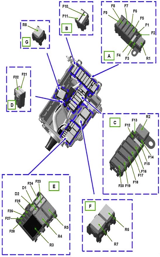
|
||
| No. | Purpose | Amps |
| R1 | Starter motor relay | 20 |
| R2 | Fuel pump relay | 20 |
| R3 | Fuel injection power relay | 40 |
| R4 | A/C compressor relay | 20 |
| R5 | Not used | - |
| R6 | High speed cooling fan relay No. 1 | 70 |
| R7 | Low speed cooling fan relay | 40 |
| R8 | High speed cooling fan relay No. 2 | 40 |
| D1 | A/C compressor clutch diode | - |
| D2 | Not used | - |
| F1 | Not used | - |
| F2 | Not used | - |
| F3 | ABS/ESP system | 25 |
| F4 | Starter motor | 30 |
| F5 | Passenger compartment fuse box | 70 |
| F6 | Passenger compartment fuse box | 70 |
| F7 | ABS/ESP system | 50 |
| F8 | Passenger compartment fuse box | 60 |
| F9 | Heated exterior mirrors | 20 |
| Heated rear window and exterior mirrors | 40 | |
| F10 | Not used | - |
| F11 | Not used | - |
| F12 | Not used | - |
| F13 | Not used | - |
| F14 | A/C compressor clutch | 15 |
| F15 | Renault Trafic 3 fuel pump fuse | 15 |
| F16 | Auxiliary heater control unit | 70 |
| F17 | Auxiliary heating element module | 60 |
| F18 | Auxiliary heating element module | 60 |
| F19 |
|
40 |
|
50 | |
| F20 |
|
40 |
| F21 | Not used | - |
| F22 | Not used | - |
| F23 | Not used | - |
| F24 | Not used | - |
| F25 | Not used | - |
| F26 | Diesel fuel heater | 25 |
| F27 | Fuel injection system | 20 |
| F28 | Fuel injection system | 15 |
