
The first-generation Saab 9-5 was built on the GM2902 platform—a modified and slightly extended (from 2,640 to 2,703 mm) GM2900 chassis shared with the Opel Vectra B. The model underwent two major facelifts: the first in 2001 and the second in 2005. In this article, we provide detailed fuse box diagrams and relay assignments for the first-generation Saab 9-5 (chassis code YS3E; 1997–2009 model years).
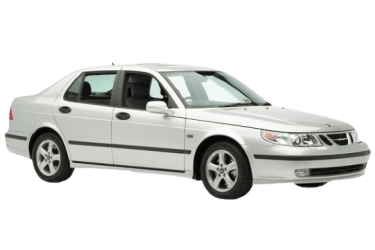
This guide details the locations and diagrams for the power distribution boxes. Fuses responsible for the “Cigarette Lighter” and “Fuel Pump” circuits are highlighted in bold.
In the Engine Compartment

Under the hood, there are two power distribution units: the main distribution box (1), housing fuses and relays, and a high-power fusible link box (2) located adjacent to the positive battery terminal.
Main Distribution Unit
Models 2002–2009

Gaining access to the main unit.
| Diagram | ||
|---|---|---|

|
||
| No. | Relay Function | |
| 1 | Bulb monitoring system, high beam headlamps | |
| 2 | Headlamp washers | |
| 3 | Front fog lamps | |
| 4 | Rear window wiper | |
| 5 | Auxiliary heater | |
| 6 | Unused | |
| 7 | Rain sensor | |
| 8 | Engine cooling fan (low speed) | |
| 9 | Engine cooling fan (high speed) | |
| 10 | A/C compressor clutch | |
| 11 | Right engine cooling fan (high speed) | |
| 12 | Horn | |
| 13 | Daytime running lights (DRL) / Interior lighting | |
| 14 | High beam headlamps | |
| 15 | Low beam headlamps | |
| 16 | Unused | |
| 17 | Windshield wiper | |
| No. | Circuit Protected | Rating |
| 1 | Engine Cooling Fan (High Speed) | 40 A |
| 2 | 2002–2004: ABS / TCS / ESP systems | 60 A |
| 2005–2009: ABS and ESP systems | 40 A | |
| 3 | 2005–2009: ABS and ESP systems | 30 A |
| 4 | Headlamp leveling sensor (Xenon) | 7.5 A |
| 5 | Auxiliary heater | 15 A |
| 6 | A/C compressor clutch, anti-theft alarm siren | 10 A |
| 7 | Bulb monitoring system, high beam headlamps | 15 A |
| 8 | Unused | — |
| 9 | Headlamp washer | 20 A |
| 10 | Left high beam headlamp | 15 A |
| 11 | Left low beam headlamp | 15 A |
| 12 | Right high beam headlamp | 15 A |
| 13 | Right low beam headlamp | 15 A |
| 14 | Engine Cooling Fan (High Speed) | 30 A |
| 15 | Front fog lamps | 15 A |
| 16 | Rear window wiper and headlamp washer | 30 A |
| 17 | Horn | 15 A |
Models 1997–2001

Relay and fuse legend on the main unit cover.
| Diagram | ||
|---|---|---|

|
||
| No. | Relay Function | |
| R1 | Windshield washer pump | |
| R2 | Low beam headlamps | |
| R3 | High beam headlamps | |
| R4 | Through 1998: Daytime running lights (DRL) | |
| R5 | Horn relay | |
| R6 | 2.0t, 2.3t: Vacuum pump | |
| R7 | Rear window wiper | |
| R8 | Engine cooling fan (low speed) | |
| R9 | Left engine cooling fan (high speed) | |
| R10 | A/C compressor clutch | |
| R11 | Front fog lamps | |
| R12 | Headlamp wiper park position | |
| R13 | Windshield wiper | |
| R14 | Right engine cooling fan (high speed) | |
| R15 | Bulb monitoring system | |
| No. | Rating | Circuit Protected |
| 1 | 60 A | Anti-lock Braking System (ABS) |
| 2 | — | Unused |
| 3 | 15 A | Horn |
| 4 | 10 A | Through 1999: Headlamp washers |
| 30 A | From 2000: Rear window wiper | |
| 5 | 15 A | Front fog lamps |
| 6 | 30 A | Engine Cooling Fan (High Speed) |
| 7 | 15 A | Right low beam headlamp |
| 8 | 15 A | Right high beam headlamp |
| 9 | 15 A | Left low beam headlamp |
| 10 | 15 A | Left high beam headlamp |
| 11 | 10 A | Headlamp washers, headlamp leveling system |
| 12 | Through 1999: Interior lighting | |
| 13 | 15 A | Bulb monitoring system |
| 14 | 10 A | A/C compressor clutch, anti-theft alarm siren |
| 15 | 30 A | Through 1999: Engine cooling fan |
| 40 A | From 2000: Right engine cooling fan | |
| 16 | 10 A | 2.0t, 2.3t: Vacuum pump |
| 17 | — | Unused |
| 18 | — | Unused |
High-Power Fusible Links
This panel is located adjacent to the positive battery terminal.

Circuit Legend :
- +30 Battery Feed (60 A);
- +30 Battery Feed (60 A);
- +30 Battery Feed (60 A);
- Ignition switch (+30, +15, +54, +X, and +B voltage supply) (60 A);
- Ignition switch relay (+54 voltage supply) (60 A).
In the Passenger Compartment
The passenger compartment contains two distribution boxes that house fuses and relays to protect internal electrical circuits.
Instrument Panel Fuse Box

Located on the left end of the instrument panel. Remove the side cover to gain access.

Overview of the Saab 9-5 cabin fuse panel.
| Diagram | ||
|---|---|---|

|
||
| No. | Circuit Protected | Rating |
| A | Through 1999: Trailer hitch connector (lighting) | 25 A |
| From 2000: Trailer hitch connector (lighting) | 30 A | |
| B | Transmission Control Module (TCM), audio system (through 1997) | 10 A |
| C | Power mirrors, Dashboard Integrated Central Electronics (DICE) module, manual headlamp leveling (from 2000) | 7.5 A |
| 1 | Brake lights, automatic transmission shift interlock | 15 A |
| 2 | Reverse lamps | 15 A |
| 3 | Left-side parking lights | 10 A |
| 4 | Right-side parking lights | 10 A |
| 5 | Integrated Central Electronics modules (DICE / TWICE) | 7.5 A |
| 6 | Right power windows, trailer battery charge circuit (from 2002) | 30 A |
| 6B | Through 2001: Trailer brake lights | 5 A |
| 2002–2004: Trailer brake lights | 10 A | |
| From 2005: Trailer brake lights | 7.5 A | |
| 7 | Fuel injectors, turbocharger bypass valve, Evaporative Emission Control (EVAP) system | 10 A |
| 8 | Trunk lamp, trunk lid release solenoid, Saab Information Display (SID), cellular phone pre-wiring, door entry lamps, Saab Park Assist (SPA), auxiliary coolant pump | 15 A |
| 9 | Audio head unit, CD changer, Diagnostic Link Connector (OBD-II DLC) | 15 A |
| 10 | Heated rear seats, power sunroof, front fog lamps, driver seat/mirror memory module (PMM) | 15 A |
| 11 | Power passenger seat, central locking (through 2004), navigation system | 30 A |
| 12 | Transmission Control Module (TCM) | 7.5 A |
| 13 | Audio head unit, audio amplifier | 20 A |
| 14 | Ignition system, direct ignition cassette, Trionic Engine Control Module (ECM), Mass Air Flow (MAF) sensor, A/C compressor, Exhaust Gas Recirculation (EGR), boost control valve | 30 A |
| 15 | Through 2001: Heated Oxygen Sensor (HO2S) | 15 A |
|
20 A | |
| 16 | Turn signals, Dashboard Integrated Central Electronics (DICE) module | 20 A |
| 16B | Through 2001: Toll transponder, OnStar telematics module | 5 A |
| From 2002: Toll transponder, OnStar telematics module | 7.5 A | |
| 17 | Trionic ECM, Main Instrument Unit (MIU), DICE/TWICE integrated electronics | 20 A |
| 18 | Through 2001: Heated power mirrors | 7.5 A |
| From 2002: Heated rear window, heated power mirrors | 40 A | |
| 19 | Through 2001: “Fuel Pump” | 20 A |
| From 2002: OnStar telematics module, cellular phone | 10 A | |
| 20 | Automatic Climate Control (ACC), interior lighting, rear fog lamp, high beam indicator | 15 A |
| 21 | Audio head unit, auto-dimming rearview mirror, headlamp leveling tilt sensor (Xenon), navigation, cruise control system | 10 A |
| 22 | 1997–2001: Blower motor/heater, Secondary Air Injection (SAI) pump (2000–2001) | 40 A |
| 2002–2004: Blower motor/heater | 30 A | |
| 2005–2009: Blower motor/heater | 40 A | |
| 23 | Through 2004: Power sunroof | 15 A |
| From 2005: Central locking, navigation, mirror memory module | 15 A | |
| 24 | Through 2001: Heated rear window | 40 A |
| 2002–2004 (3.0 V6 engine): Secondary Air Injection (SAI) pump | 40 A | |
| From 2006: Headlamp switch | 20 A | |
| 25 | Power driver seat, fuel filler door release solenoid | 30 A |
| 26 |
|
7.5 A |
| 27 | Trionic ECM, Saab Information Display (SID), seatbelt warning chime (1997–2001), Main Instrument Unit (MIU), DICE module, Saab Park Assist (SPA) (1997–2001) | 10 A |
| 28 | Supplemental Restraint System (SRS) / Airbag control unit | 7.5 A |
| 29 | Through 2004: Transmission Control Module (TCM); From 2002: ABS / TCS / ESP control systems |
7.5 A |
| 30 | Starter motor relay, Transmission Control Module (TCM) (2006–2009) | 7.5 A |
| 31 | Cruise control, headlamp leveling, Automatic Climate Control (ACC), Manual Climate Control (MCC), front fog lamps (2005–2009), rain sensor, heater coolant bypass valve | 7.5 A |
| 32 | 1997–2005: Ventilated front seats | 15 A |
| 33 | Turn signal flasher | 7.5 A |
| 34 | “Cigarette Lighter” / 12V power sockets (front and rear) | 30 A |
| 35 | Daytime running lights (DRL) | 15 A |
| 36 | Left power windows | 30 A |
| 37 | Windshield wipers, front fog lamps (1997–1999) | 30 A |
| 38 | Heated front seats | 30 A |
| 39 |
|
20 A |
Relay Panel

Located under the instrument panel on the driver side.

Relay Legend:
- A – Unused;
- B – Heated rear seats;
- C1 – Unused;
- C2 – Auxiliary heater;
- D – 3.0 TiD V6 engine: Secondary Air Injection (SAI) pump;
- E – Trionic Engine Control Module (ECM);
- F – Fuel filler door release solenoid;
- G – Gasoline: “Fuel Pump” relay / Diesel: Glow plug preheater;
- H – Ignition switch;
- I – Heated rear window and heated power mirrors;
- J – Through 2001: Reverse lamps;
- K – Starter motor;
- L1 – Throttle body limp-home system;
- L2 – Trunk release solenoid.
