The Volkswagen Amarok pickup was produced in 2009, 2010, 2011, 2012, 2013, 2014, 2015, 2016. Then the car was restyled and the updated one is being produced from 2017 to the present. There are 3 trim levels in Amarok - Trendline, Comfortline and Highline with diesel and petrol engines. In our material you can familiarize yourself with the description of fuse blocks and relays Volkswagen Amarok, their diagrams and photographs. Separately, we note the fuse for the cigarette lighter.
General layout
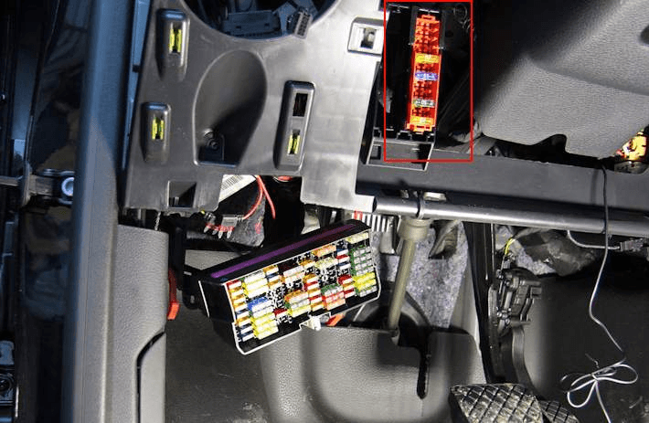
For all Volkswagen Amarok models, the following arrangement is characteristic: the main block with fuses and relays in the passenger compartment and the block on the battery cover. But depending on the level of electrical equipment, it is possible to place both an additional unit and individual elements, especially for cars manufactured after 2013.

- Fuse 1 for fresh air blower -S97- and fuse 1 for ABS control unit
- Fuse holder C -SC- (72/68 fuses)
- 3Fuse-link block on the cover AKB (SA)
- Battery fuse box (SB)
In the passenger compartment
Main fuse box
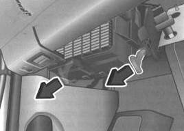
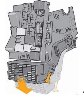
It is located under the dashboard on the driver's side. To access the fuses, you must release the locking lever. The fuse box can then be folded down.
Access example.
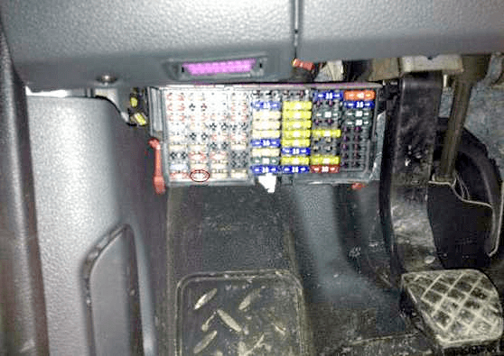
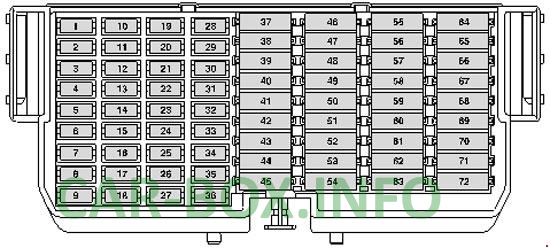
models up to 2013
General view.
| Diagram | |
|---|---|
|
|
| Type 1 | |
| № | Description |
| 1 | 10A ABS control unit, ASR and ESP deactivation key, Drive program key |
| 2 | 10A Heating resistor for left windscreen washer jet, Steering column switch block, Wiper switch, Washer pump and headlight cleaning system switch |
| 3 | 10A Reversing light switch, Parking aid control unit / 15A Onboard power supply control unit, Reversing light lamps, Interface for external use |
| 4 | 15A Onboard supply control unit, Direction indicator (terminal 49), Brake light (terminal 54) |
| 5 | 5A Air mass meter |
| 6 | 5A Trailer recognition control unit |
| 7 | 5A Interface for external use |
| 8 | 5A Ignition and starter switch / 15A Ignition and starter switch |
| 9 | 10A Airbag control unit, Front passenger airbag deactivation warning lamp |
| 10 | 5A Engine control unit |
| 11 | 15A Differential lock control unit |
| 12 | 10A Fuel pressure regulator, Fuel metering valve, Bypass valve for turbocharger, Solenoid valve for boost pressure limitation, Solenoid valve 1 of the adsorber, Valve 1 of the intake camshaft timing regulator, Valve for inlet flaps |
| 13 | 5A Exhaust gas flap valve, Exhaust gas recirculation cooler changeover valve, Charge pressure limiting solenoid valve |
| 14 | 15A Coolant circulation pump after engine shutdown, fuel pressure regulator |
| 15 | 5A Power supply relay cl. 30, Circulation pump |
| 16 | 10A Rear fog lamp / 5A Voltage stabilizer, Data bus diagnostic interface |
| 17 | 5A Onboard supply control unit |
| 18 | 7,5A Washer pump |
| 19 | 15A Onboard supply control unit, Heated exterior mirrors |
| 20 | 15A Onboard supply control unit, internal power supply |
| 21 | 10A Onboard power supply control unit, Interior protection shutdown switch, Interior lighting, Parking lights |
| 22 | 5A Position tracking control unit |
| 23 | 10A Engine control unit |
| 24 | 10A Alarm Siren |
| 25 | 10A Heating resistor for crankcase ventilation |
| 26 | 5A Lamp of the right module of daytime lighting |
| 27 | 5A Lamp left module daytime running light |
| 28 | 5A Light switch, License plate light, Connection 8 in the main wiring harness / 15A Onboard supply control unit, fog lamps, Reversing lamps, Interface for external use |
| 29 | 10A Left headlight range control actuator, Left headlamp low beam lamp, External interface / 5A Light switch |
| 30 | 10A Left high beam headlight lamp, Instrument cluster control unit, External user interface / 5A Starter relay |
| 31 | 5A Tiptronic switch, Automatic gearbox control unit |
| 32 | 10A Lamp of the right high beam headlamp |
| 33 | 5A Outside mirror adjuster |
| 34 | 15A Engine control unit |
| 35 | 15A Lambda probe heating element |
| 36 | 5A Fuel pump relay, power supply relay cl. 30, Clutch pedal switch, Radiator fan control unit, Glow plug control unit |
| 37 | 20A Ignition coil |
| 38 | 15A Socket 12V |
| 39 | 25A Trailer recognition control unit |
| 40 | 25A Trailer recognition control unit |
| 41 | 25A Trailer recognition control unit |
| 42 | 15A Brake light switch, High pressure sensor, Air pollution sensor, Oil level and temperature sensor, Differential lock control unit, Instrument cluster control unit, Parking aid control unit, Transfer case control unit, Position tracking control unit, Normal mode indicator on the transfer case control panel, Fuse 16 on fuse box C, Diagnostic connector, Steering column switch box, Steering angle sensor, Cruise control switch |
| 43 | 25A Onboard supply control unit, Wiper motor control unit, Wiper motor |
| 44 | 30A Onboard supply control unit, Heated rear window |
| 45 | 15A Diagnostic connector, Control unit in dash panel insert, Air conditioning control unit, Climatronic control unit, Heater and operating mode selector switch, Steering column switch, Coiled cable, Multifunction steering wheel control unit |
| 46 | 25A Transfer case control unit |
| 47 | 20A Onboard supply control unit, high tone signal, low tone signal |
| 48 | 20A Driver's door control unit |
| 49 | 20A Front passenger door control unit |
| 50 | 20A Rear left door control unit |
| 51 | 20A Rear right door control unit |
| 52 | 15A Socket |
| 53 | 20A Fog lamps / 25A Onboard supply control unit |
| 54 | 15A Cigarette lighter |
| 55 | 15A Right headlight range control actuator, Right dipped beam headlamp, External user interface / 25A Onboard supply control unit, Right daytime running light module, Right dipped beam headlamp, Interface for external use |
| 56 | 25A Fuel pump control unit |
| 57 | 30A Seat heating button, Seat heating control unit |
| 58 | 15A Tiptronic switch, Automatic gearbox control unit, Key removal lock solenoid |
| 59 | 20A Socket 12V 2 |
| 60 | 5A Trailer recognition control unit |
| 61 | 5A Trailer recognition control unit |
| 62 | 20A Auxiliary heater control unit, Coolant pump relay, Auxiliary water heater relay, Circulation pump |
| 63 | 10A Load platform illumination lamp |
| 64 | 40A Heater switch and operating mode selection, Climatronic control unit, Air conditioning control unit |
| 65 | 15A Engine control unit |
| 66 | 30A Onboard supply control unit, filler flap central locking actuator, central locking actuator |
| 67 | 30A Head unit, Control unit with display for radio navigation system, Voltage stabilizer, Data bus diagnostic interface |
| 68 | 7.5A Telephone control panel control unit |
| 69 | 15A Interface for external use |
| 70 | 5A Interface for external use |
| 71 | 25A Interface for external use |
| 72 | 10A Interface for external use |
| Fuse number 54, 15A, is responsible for the cigarette lighter. | |
| Type 2 | |
| № | Legend |
| 1 | 10A ABS control unit ASR and ESP deactivation key Travel program key Airbag control unit Front passenger airbag deactivation indicator Light switch |
| 2 | 10A Block of understeering switches Wiper switch Intermittent wiper switch Switch for window washer pump and headlight cleaning system |
| 3 | 15A Switch Lighting heater switch, and select the operating mode the air conditioner control unit Potentiometer executive motor front air distribution flap Climatronic control unit Relay for auxiliary water heater Circulation pump |
| 4 | 15A Engine control unit Air mass meter |
| 5 | 5A Air mass meter |
| 15A Ignition coil | |
| 6 | 5A Trailer recognition control unit |
| 7 | 5A Interface for external use |
| 8 | 15A Ignition and starter switch Alarm siren Control unit for vehicle position tracking |
| 9 | 5A Load platform illumination lamp |
| 10 | 5A Tiptronic switch Automatic gearbox control unit Air mass meter Engine control unit |
| 11 | 15A Differential lock control unit |
| 12 | 10A Solenoid valve for boost pressure limitation Solenoid valve 1 of the adsorber Valve 1 of the inlet camshaft control valve Turbocharger bypass valve Intake manifold flap Fuel pressure regulator Fuel metering valve |
| 13 | 7.5A Left seat heating button Right seat heating button Heating resistor for left windscreen washer jet Heating resistor for right windscreen washer jet |
| 14 | 15A Fuel pressure regulator -N276 |
| 15 | 5A Power supply relay cl. thirty Circulation pump |
| 16 | 10A Rear fog lamp warning lamp Left fog lamp Right fog lamp lamp |
| 5A Voltage stabilizer | |
| 17 | 5A Onboard supply control unit |
| 18 | 7,5A Washer pump |
| 10A Washer pump | |
| 19 | 10 / 15A Onboard supply control unit Heated outside mirror, driver's side Outside mirror heating element, passenger side |
| 20 | 15 / 5A Onboard supply control unit Internal power |
| 21 | 15A Onboard supply control unit Interior protection shutdown switch Front courtesy light Central courtesy light Front side light, left Front side light, right |
| 22 | Not used |
| 10A Rear view camera control unit | |
| 23 | 10A Engine control unit |
| 24 | 5A Block of understeering switches Switch for low beam and light signal (including high beam) |
| 25 | 10A Heating resistor for crankcase ventilation |
| 26 | 5A Lamp of the right module of daytime lighting |
| 27 | 5A Lamp left module daytime running light |
| 28 | 5A B472 Connection 8 in the main wiring harness Light switch Headlight range control knob License plate light, left License plate light, right |
| 15A Onboard supply control unit Left fog lamp bulb Right fog lamp Right reversing lamp lamp Left reversing lamp lamp External interface |
|
| 29 | 10A Lamp of the left low beam headlamp Interface for external use |
| 5A Light Switch | |
| 30 | 10A Lamp for left main beam headlight Control unit in dash panel insert Interface for external use Onboard supply control unit |
| 31 | 5A Interface for external use |
| 32 | 10A Lamp of the right high beam headlamp |
| 33 | 5A Outside mirror adjuster |
| 34 | 15A Engine control unit Coolant circulation pump after off. engine |
| 35 | 15A Lambda probe heating element |
| 36 | 5A Fuel pump relay Power supply relay cl. 30 Clutch pedal switch |
| 37 | 20A Ignition coil |
| Not used | |
| 38 | 40A Fuse 28, 29, 50 in the fuse box Fuel pump relay Head light relay Starter relay Main relay Unload relay cl. 58b |
| 39 | 25A Trailer recognition control unit |
| 40 | 25A Trailer recognition control unit |
| 41 | 41A Trailer recognition control unit |
| 42 | 10 / 15A, key start-stop mode switch stoplights reversing light switch Tachograph high pressure sensor air pollution sensor level sensor and an oil temperature lock control unit differential unit parking aid control management block transfer case control lamp normal mode on the control panel transfer case control downshift lamp on the transfer case control panel Center differential lock control lamp on the transfer case control panel High brake light lamp Diagnostic connector Steering column switch block Steering angle sensor Cruise control switch Cruise control SET key Spiral cable Multifunction steering wheel control unit |
| 43 | 30A Onboard supply control unit Wiper motor control unit Wiper motor |
| 25A light switch | |
| 30A Voltage stabilizer Instrument cluster control unit Fuse 67 on fuse box C |
|
| 44 | 30A Onboard supply control unit Heated rear window relay Rear window heating element |
| 45 | 15 / 10A mode heater and the selection switch operation Diagnostic connector unit dash panel Climatronic control unit fan sensor regulation Bitron, Front Rain sensor and light sensor protection cabin system telephone operating unit control unit Tachograph switch Tiptronic lock solenoid extracting the ignition key switch of the electric fuel pump 2 Ceiling display panel Radio receiver for auxiliary coolant heater Steering column switch block Spiral cable Multifunction steering wheel control unit |
| 46 | 25 / 30A Transfer case control unit |
| 47 | 25A Onboard supply control unit High tone horn Low tone signal |
| 48 | 30A Driver door control unit |
| 49 | 30A Front passenger door control unit |
| 50 | 30A Rear left door control unit |
| 51 | 30A Rear right door control unit |
| 52 | 30A Socket Cigarette Lighter |
| 53 | 25 / 20A Onboard supply control unit Lamp, left daytime running light module Left low beam headlamp bulb |
| 54 | 20A light switch |
| 55 | 15 / 10A Headlamp leveling regulator Right headlight low beam lamp Interface for external use |
| 25 / 20A Onboard supply control unit Right daytime running light module lamp Right low beam headlamp bulb Interface for external use |
|
| 56 | 25A Fuel pump control unit |
| 57 | 30 / 25A Seat heating control unit |
| 58 | 15A Tiptronic switch Automatic gearbox control unit Solenoid for locking the key removal from the ignition lock |
| 30A Onboard supply control unit Wiper motor control unit Wiper motor |
|
| 59 | 25A Socket 12V 2 and 3 |
| 60 | 20A Left fog lamp Right fog lamp External interface |
| 5A Interface for external use | |
| 61 | 30 / 15A Onboard supply control unit Left fog lamp bulb Right fog lamp bulb Right reversing light bulb Left reversing lamp Interface for external use |
| 62 | 20A Additional heater control unit Supply fan relay Electric fuel pump relay 2 Ceiling display panel Radio signal receiver for auxiliary water heater Cooling pump relay |
| 15A Additional heater control unit Supply fan relay Cooling pump relay |
|
| 30A Additional heater control unit Supply fan relay Relay for electric fuel pump 2 Ceiling display panel Radio signal receiver for additional water heater |
|
| 63 | 30A Light Switch |
| 5A Light switch Starter relay 1 Starter relay 2 |
|
| 64 | 40A Supply fan |
| 65 | 15A Onboard supply control unit Direction indicator (cl. 49) Stop light (terminal 54) |
| 66 | 30A Onboard supply control unit Central locking actuator for the filler flap Driver's door central locking drive Front passenger door central locking drive Rear left door central locking drive Rear right door central locking drive |
| 67 | 30A Control unit with display for radio navigation system Head unit Voltage regulator Instrument cluster control unit Control unit with display for radio navigation system Head device |
| 25A Head unit Control unit with display for radio navigation system |
|
| 68 | 40A Switch for heater and operating mode selection Air conditioning control unit Supply fan isolating relay Air conditioner control unit |
| 69 | 15A Interface for external use |
| 70 | Not used |
| 40 / 30A Starter relay 1 Starter relay 2 |
|
| 71 | 30A Interface for external use |
| 72 | 5 / 10A Interface for external use |
| In this version, fuse number 52 is responsible for the cigarette lighter. | |
Models from 2013 release
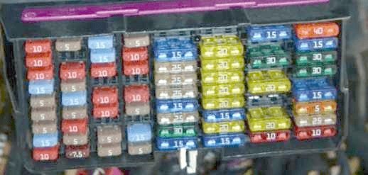
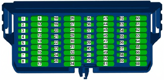
Since July 2013, a new 68-socket SC fuse box (under the dash on the driver's side) has been installed on Volkswagen Amarok vehicles. It differs from the old 72-socket block first of all visually in that vertical rows of smaller fuses (MINI, 8 pieces per row) alternate with rows of larger fuses (ATO, 9 pieces per row). In the old 72 - socket block, first there were 4 rows of MINI fuses, then 4 rows of ATO fuses, 9 pieces in all rows.
General view.
| Diagram | |
|---|---|
|
|
| № | Description |
| 1 | 10A Washer pump |
| 2 | 15A Heater and operating mode selection switch Bitron fan control sensor, front Climatronic control unit Air conditioning control unit Control unit for vehicle position tracking Control unit for automatic gearbox Onboard supply control unit Internal power |
| 3 | 15A Ignition and starter switch Control unit for vehicle position tracking Onboard supply control unit Internal power |
| 4 | 15A Alarm siren Power supply relay cl. thirty Steering column switch block Switch for low beam and light signal (including high beam) |
| 5 | 15A Differential lock control unit |
| 6 | 15A Onboard supply control unit Left fog lamp bulb Right fog lamp bulb Left reversing lamp Right reversing light bulb Interface for external use |
| 7 | 15A Onboard supply control unit Interior protection shutdown switch Front courtesy lamp Central courtesy light Front side light, left Front side light, right |
| 8 | 15A Trailer detector control unit -J345- |
| 9 | 40 / 30A Relay for headlights Relay for starter Relay for power supply Motronic Relay for unloading cl. 58b |
| 10 | 20A Trailer recognition control unit |
| 11 | 20A Trailer recognition control unit |
| 12 | 30A Transfer case control unit |
| 13 | 30A Driver door control unit |
| 14 | 30A Front passenger door control unit |
| 15 | 20A Cooling pump relay Power supply relay cl. 30 Relay for auxiliary coolant heater Control unit for auxiliary heater |
| 30A Supply fan relay Power supply relay cl. 30 Relay for auxiliary coolant heater Control unit for auxiliary heater |
|
| 20A Additional heater control unit | |
| 16 | 20A Onboard supply control unit Direction indicator (cl. 49) Stop light (terminal 54) |
| 17 | 25A Control unit with display for radio navigation system Head unit Connector, 8-pin |
| 18 | 5A Instrument cluster |
| 19 | 10 / 5A Left fog lamp Right fog lamp Rear fog lamp warning lamp |
| 20 | 5A Onboard supply control unit |
| 21 | 5A Lamp, left daytime running light module Lamp, right daytime running mode |
| 22 | 10A Positive connection (58 D1) in the wiring harness of the instrument cluster and controls B342 Connection 3 (58d) in the main wiring harness B472 Connection 8 in the main wiring harness N2 Connection 1 in the headlight range control wiring harness R14 Connection 1 (open) in the wiring harness driver's door |
| 23 | 5A Clutch pedal switch Air mass meter Fuel pump relay Glow plug control unit Cooling pump relay Radiator fan control unit Cl. 30 Solenoid valve for charge pressure control Exhaust gas flap valve Changeover valve for exhaust gas recirculation cooler |
| 24 | 10A Fuel pressure regulator Fuel metering valve |
| 10A Solenoid valve for boost pressure control Solenoid valve 1 of the adsorber Valve 1 of the inlet camshaft control valve Turbocharger bypass valve Intake manifold flap valve |
|
| 25 | 5A Coolant circulation pump after engine shutdown |
| 15A Engine control unit | |
| 26 | 7.5A / 10A Interface for external use Left headlight headlamp Left headlight dipped beam lamp |
| 27 | 10 / 15A Onboard supply control unit Left headlight Headlamp Right headlight Interface for external use Instrument cluster control unit High beam indicator lamp |
| 28 | 10A Interface for external use Right headlight Right low beam headlamp bulb |
| 29 | Not used |
| 10A Tiptronic switch Tachograph Solenoid for blocking the removal of the key from the ignition switch Radio signal receiver for additional water heater Diagnostic connector Steering column switch block Spiral cable Multifunction steering wheel control unit |
|
| 30 | 5A Interface for external use Interface for external use |
| 20A Left fog lamp Right fog lamp lamp External interface |
|
| 31 | 15 / 30A Interface for external use Ignition and starter switch Power supply relay cl. 15 Onboard supply control unit Steering column switch block Switch for window washer pump and headlight cleaning system |
| 32 | 15A Lambda probe heating element Lambda probe 1 heating element after catalytic converter |
| 33 | 15A Ignition coil |
| 20A Air Mass Sensor Engine Control Unit |
|
| 34 | 20A Fuel pump control unit Booster fuel pump |
| 35 | 5A Button for heating the left seat Button for heating the right seat |
| 36 | 5A Outside mirror adjuster |
| 37 | 15A Interface for external use |
| 38 | 5A Tiptronic switch Automatic gearbox control unit -J217-Air mass meter Engine control unit Voltage stabilizer |
| 39 | 10A Airbag control unit Front passenger airbag deactivation warning lamp |
| 40 | 5A Heater and operating mode selection switch ASR and ESP deactivation button Driving program button ABS control unit Anti-theft alarm relay 1 Instrument cluster Paddle switch block Steering angle sensor |
| 41 | 10A Headlamp leveling adjuster Trailer detector control unit Crankcase ventilation heating resistor 8-pin connector Electrochromic interior rearview mirror Left headlight range control actuator Right headlight range control motor Right washer jet heating resistor Right windscreen washer jet heating resistor |
| 42 | 10A, key start-stop mode switch stoplights reversing switch lights Tachograph high pressure sensor air pollution sensor level sensor and an oil temperature lock control unit differential unit parking aid control management block transfer case control lamp normal mode on the control panel of the transfer case Backlight Truck platforms Diagnostic connector Vehicle position tracking control unit Instrument cluster Steering column switch block Cruise control switch Set key (SET) cruise control Spiral cable Multifunction steering wheel control unit |
| 43 | 25A Socket / Cigarette Lighter |
| 44 | 20A light switch |
| 45 | 25A Seat heating control unit |
| 46 | 25A 12V socket 2 12V socket 3 |
| 47 | 5A Interface for external use Interface for external use Ignition and starter switch Power Relay Onboard supply control unit Power supply relay 2 Heater switch and operating mode selection |
| 48 | 25A Control unit with display for radio navigation system Head unit Connector, 8-pin |
| 49 | 5A Light switch Starter relay 1 Starter relay 2 |
| 20A light switch | |
| 50 | 5A Interface for external use |
| 51 | 30A Starter relay 1 Starter relay 2 Starter |
| 52 | 5A Interface for external use |
| 53 | 5A Control unit for special construction Load platform lighting lamp |
| 10 / 15A Switch for heater and operating mode selection Tachograph Fan control sensor Bitron, front Climatronic control unit Air conditioning control unit |
|
| 54 | 5A Instrument cluster |
| 55 | 15A Onboard supply control unit Interference filter Heating element for exterior mirrors |
| 56 | 10A Rear view camera control unit |
| 57 | 5A Engine control unit |
| 58 | 5A Light Switch |
| 59 | 10A Tiptronic switch Tachograph Interior monitoring sensor Rain and light sensor Relay for electric fuel pump 2 Ceiling display panel Control unit for telephone control panel - Solenoid for key removal from the ignition key Radio signal receiver for auxiliary water heater Diagnostic connector Control unit for special superstructures Load bed lighting lamp Pump relay cooling systems Power supply relay cl. 30 Relay for auxiliary coolant heater Steering column switch block Spiral cable Multifunction steering wheel control unit |
| 60 | 25A Onboard supply control unit Central locking actuator for the filler flap Central locking drive |
| 61 | 15A Light Switch |
| 25A Voltage stabilizer Fuse 18, 48 in fuse box C |
|
| 62 | 30A Onboard supply control unit Rear window heating element Heated rear window relay |
| 63 | 30A Onboard supply control unit High tone horn Low tone signal Anti-theft alarm buzzer Anti-theft alarm relay 1 External interface |
| 64 | 30A Rear left door control unit |
| 65 | 30A Rear right door control unit |
| 66 | 20A Onboard supply control unit Left headlight headlight |
| 67 | 20A Onboard supply control unit The right headlight of head light bulb lamp left Reversing lamp right reversing light |
| 68 | 30A Onboard supply control unit Wiper motor control unit Wiper motor |
Additional elements
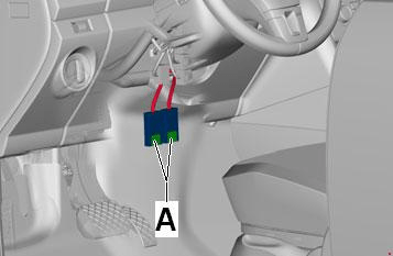
Next to the steering rack, an additional fuse box or separate elements can be located.
|
|
| 40 | Supply fan, Switch for heater and operating mode selection, Air conditioning control module |
| 40 | ABS control module |
Relay box
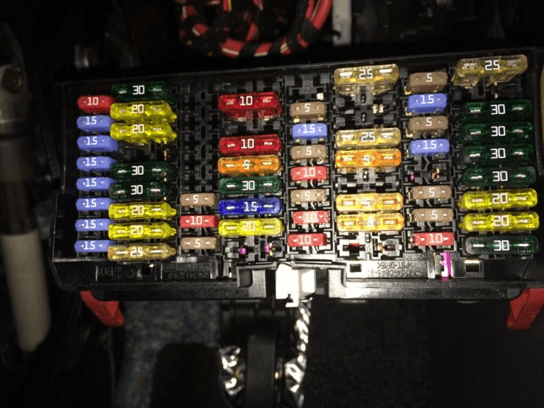
It is located on a bracket on the driver's side under the dashboard. The relay box bracket is completely hidden by the instrument panel. The SC fuse box is also attached to the same bracket. There may also be an onboard power supply control unit integrated in the relay / fuse box (SC) bracket itself.
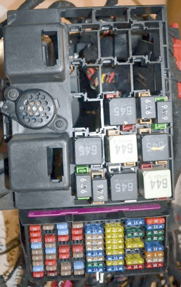
Photo - example.
In the engine compartment
High power fuses in the form of fusible links (SA) are located under the cover on the battery. It is connected to the battery positive terminal wire. A fuse box (SB) is located nearby, protected from water by a special cap.

Diagram
Decoding SA
- 175A - Generator
- 110 / 175A - Relay and fuse in the passenger compartment
- 110A - Relay and fuse in the passenger compartment, 50A - fuses in the passenger compartment or interface for external use
- 80 / 110A Radiator fan control unit
- 50A - Glow plug control unit
- 80 / 110A - Fuses in the cabin
Panel SB appointment
- 40A - ABS control unit, 25A - Main relay
- 30A - Fuel Pump Relay, Fuel Delivery Module, Fuel Pressure Regulator, Electric Fuel Pump Relay 2, Fuel Delivery Module
- 30A - ABS control unit
- 5A - Control unit for battery monitoring, Onboard supply control unit
- 7.5A - Blower relay, 30A - High beam relay, high beam headlamps, 25 / 40A - Heated rear window relay, Heated hard top rear window
- 40A - Connector, 6-pin or Interface for external use

Thanks for the comprehensive article. My 2016 2 litre Amarok right hand drive (Australian registration) has lost all reverse sensors - the 4 at the rear, and the 4 at the front installed in my "roo bar". Additionally, and at the same time, I lost my reverse camera. All that happens now when I select reverse is the dash button illuminates and a constant alarm sounds, but that's all. I can't locate the appropriate fuse from the above lists. Hope you can steer me in the right direction for a fix. Thanks.