
The Crafter is available in several body configurations: passenger van, chassis cab, and crew cab/combivan. First-generation production years: 2006, 2007, 2008, 2009, 2010, 2011, 2012, 2013, 2014, 2015, and 2016 (including the mid-cycle facelift). The second-generation updated Crafter has been in production since 2017. This article provides detailed information on the Crafter's (first generation; chassis codes 2E, 2F; LT3 / VN84X platform) fuse and relay boxes, including assignment diagrams, locations, and photographs. The fuse for the cigarette lighter is highlighted in bold.
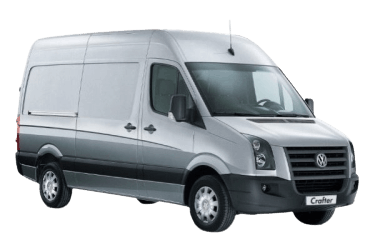
Depending on the vehicle’s trim level (Standard, Highline, etc.) and model year, fuse box configurations and relay assignments may vary.
General Overview

The Crafter features the following fuse and relay locations:
- Main power supply fuse, Terminal 30 -S190-
- Pre-fuse box at battery -SA-
- Fuse holder B, left A-pillar -SB-
- Fuse and relay box C, left dash -SC-
- Fuse and relay holder under driver’s seat -SD-
- Auxiliary fuses under driver’s seat
Main Power Supply Fuse (Terminal 30)
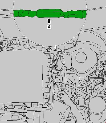
The main power supply fuse (Terminal 30) is located in the wiring harness between the alternator and the starter motor.
Pre-Fuse Box at Battery
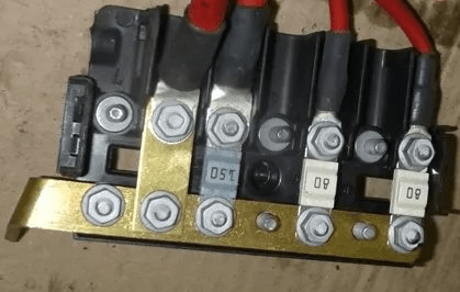
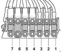
Houses high-current fusible links.
| Diagram | |
|---|---|
|
|
| No. | Rating / Protected Component |
| 1 | 80A Glow plug control module |
| 2 | 40A / 60A / 80A Radiator fan control module, Radiator fan motor |
| 3 | 80A Body Control Module (BCM), Engine electronics power supply relay, Fuse Box C |
| 4 | 150A Auxiliary battery, Bodybuilder main fuse, Fuse Box D |
| 5 | 150A Terminal 15 power supply relay, Horn relay, Body Control Module (BCM), Fuse Box B or Fuse Box C |
| 6 | Terminal 15 load reduction relay, Power supply relay 1, Heated windshield fuse, Fuse Box D |
| 7 | 150A Auxiliary air heater element |
Left-Side Fuse Boxes
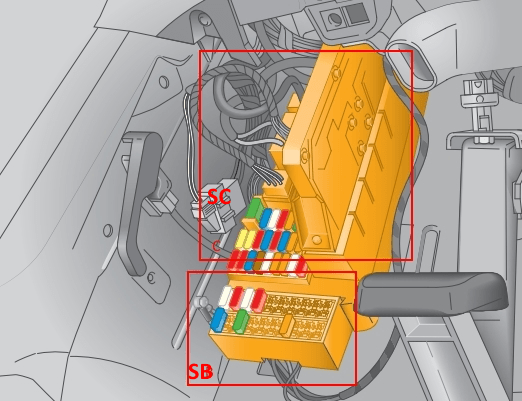
Located in the left footwell underneath the dashboard. Consists of two sections: Fuse Box B and Fuse & Relay Box C.
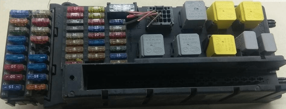
Location overview.
Fuse Box -SB-
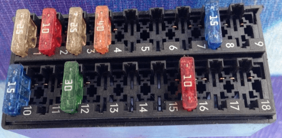
General view.
| Diagram | |
|---|---|

|
|
| No. | Rating / Circuit |
| 1 | 25A Driver door control module |
| 2 | 10A Diagnostic link connector (OBD-II / T16) |
| 3 | 25A ABS control module |
| 4 | 40A ABS control module |
| 5 | Vacant |
| 6 | Vacant |
| 7 | 30A Headlight washer pump |
| 8 | 15A Anti-theft alarm system relay 1 |
| 9 | Vacant |
| 10 | 15A Radio / Navigation system head unit |
| 11 | 7.5A Mobile phone interface control module, Tachograph control module |
| 12 | 30A Heater fan control switch, Blower motor relay |
| 13 | 7.5A Auxiliary heater timer unit |
| 14 | 30A Driver and front passenger heated seat control modules |
| 15 | 10A Cargo area lighting switch |
| 16 | 10A Blower control unit, A/C control panel, CD changer |
| 17 | 10A Interior lighting switch |
| 18 | Vacant |
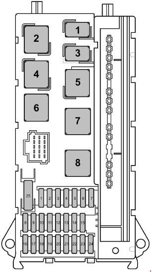
Fuse Box -SC-
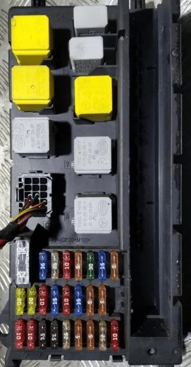
General view.
| Diagram | |
|---|---|
|
|
| No. | Rating / Circuit |
| 1 | 15A High-tone horn |
| 2 | 25A Electronic ignition lock (EIS), Electronic steering column lock module |
| 3 |
|
| 4 | 5A Headlight switch, Center console switch panel |
| 5 | 30A Windshield wiper motor |
| 6 | 15A Auxiliary fuel lift pump |
| 7 | 5A Steering column electronics module |
| 8 | 20A Engine Control Module (ECM) |
| 9 |
|
| 10 |
|
| 11 | 15A Terminal 15 load reduction relay 2 (3.8t GVWR models only), Fuses 1 & 2 in Fuse Holder D |
| 12 | 10A Airbag Control Module (ACM) |
| 13 | 15A Glove compartment light switch, Cigarette lighter |
| 14 | 5A Headlight switch, Instrument cluster control module, Diagnostic link connector |
| 15 | 5A HVAC control unit, Headlight range adjustment switch, Left and right headlight range control actuators |
| 16 |
|
| 17 | 10A Airbag Control Module (ACM) |
| 18 |
|
| 19 | 7.5A Body Control Module (BCM) (Interior lighting circuit) |
| 20 | 25A Body Control Module (BCM) |
| 21 |
|
| 22 |
|
| 23 | 25A Starter motor, Body Control Module (BCM) |
| 24 | 10A Spare (Terminal 15), Battery monitoring control module (from May 2013) |
| 25 | 30A 12V auxiliary power socket |
| 1 | Horn relay |
| 2 | Windshield wiper speed changeover relay 2 |
| 3 | Fuel pump relay |
| 4 | Windshield wiper speed changeover relay 1 |
| 5 | Terminal 50 power supply relay |
| 6 | Terminal 15 power supply relay |
| 7 | Engine management power supply relay |
| 8 | Terminal 15 power supply relay 2 |
Fuse Box -SD-
Located under the driver’s seat.

Location overview.
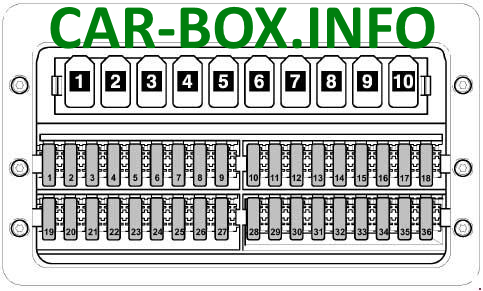
Type 1
Assignment diagram.
|
|
| No. | Rating / Circuit |
| 1 | 5A Power window control panel (driver door), Heated rear window relay (up to Jun 2006), Heated rear window relay 2 (from Jul 2006) |
| 2 | 30A Rear window wiper motor (hinged doors) |
| 3 | 5A Auxiliary heater timer, Neutral position switch, Display unit, Hands-free cell phone module (up to May 2011), Rearview camera system |
| 4 | 7.5A Engine speed governor switch (from Jul 2006), Power Take-Off (PTO) monitoring sensor (from Jul 2006), Heated rear window relay (up to Jun 2006), Trailer recognition control module, Tachograph module (from Jul 2006) |
| 5 | 5A / 10A Gear selector switch, Automated manual transmission control module |
| 6 | 5A Battery monitoring control module (up to May 2013), Crankcase ventilation heating element |
| 7 | 10A Fuel filter heater element |
| 8 | 5A / 10A Tipper body control switch, Terminal 15 bodybuilder relay, 6-pin bodybuilder connector (from May 2007), 7-pin tail-lift interface connector |
| 9 | 15A Roof vent fan switch (cargo intake/exhaust), Alarm siren relay |
| 10 | 25A Special equipment / bodybuilder circuit |
| 11 | 15A Terminal 15 bodybuilder relay |
| 12 | 10A Terminal 61 bodybuilder relay |
| 13 | 10A / 30A Roof A/C evaporator fan control module (May 2007 – May 2011), Roof-mounted hazard/turn signal relay (up to May 2007) |
| 14 | 20A Trailer recognition control module (up to Aug 2006), 9-pin trailer pre-installation socket (from Sep 2006), Trailer hitch socket (from Sep 2006) |
| 15 | 25A Trailer recognition control module |
| 16 | 7.5A Park Distance Control (PDC) module, Tire Pressure Monitoring System (TPMS) module |
| 17 | 25A Programmable Special Function Module (PSM) |
| 18 | 25A Programmable Special Function Module (PSM) |
| 19 | 5A / 25A Overhead console control module |
| 20 | 7.5A / 10A After-run coolant pump relay, Entry/footwell lighting relay (from May 2009) |
| 21 | 15A / 30A Rear window defogger relay |
| 22 | 15A Rear window heating relay (up to Jun 2006), Rear window heating relay 2 |
| 23 | 10A / 15A Cargo box lighting switch (from Nov 2008), 12V power socket 2 |
| 24 | 15A 12V power socket 4 |
| 25 | 15A 12V power socket 3 |
| 26 | 25A Auxiliary heater control unit |
| 27 | 20A / 25A Auxiliary heater control unit |
| 28 | 30A / 40A Evaporator blower module (up to Apr 2007), Automated manual transmission hydraulic pump relay (from May 2007) |
| 29 | 15A Automated manual transmission control module |
| 30 | 40A Transmission hydraulic pump relay (up to Apr 2007), Battery monitoring control module |
| 31 | 15A / 30A Rear climate control intake blower module, Left power sliding door control module, Rear intake blower motor |
| 32 | 5A Battery monitoring system sensor/module |
| 33 | 15A Right power sliding door control module |
| 34 | 15A AdBlue/DEF heating system control module (from Apr 2009) |
| 35 | 15A / 30А AdBlue/DEF heating system control module (from Apr 2009) |
| 36 | Vacant |
| Relay Assignments: 1 - Terminal 15 special bodybuilder relay 2 - Terminal 61 special bodybuilder relay 3 - Interior lighting relay / Tipper control relay (up to Oct 2007) / Tailgate relay 4 - Headlight washer system relay 5 - Rotating beacon light relay 6 - Anti-theft alarm system relay 1 7 - Coolant pump relay 8 - After-run coolant circulation pump relay 9 - Alarm siren relay 10 - Vacant |
|
Type 2
Assignment diagram.

|
|
| No. | Rating / Circuit |
| 1 | 5A Driver door window switch block, Heated rear window relay 2 |
| 2 | 30A Rear window wiper motor (hinged doors) |
| 3 | 5A Auxiliary heater timer unit, Neutral safety switch, Display panel module, Rearview camera |
| 4 | 7.5A Engine speed governor switch, PTO sensor, Trailer recognition control module, Tachograph module |
| 5 | 5A / 10A Selector lever module, Automated manual transmission control module, Hood contact switch (from Nov 2011) |
| 6 | 5A / 10A Crankcase ventilation heater resistor, Battery monitoring control module (May 2011 – May 2013) |
| 7 | 10A Fuel filter heater element |
| 8 | 5A / 10A Tipper switch, Park Distance Control module (from May 2013), Terminal 15 bodybuilder relay (up to Nov 2011), 6-pin connector -T6ah-, 7-pin tail-lift connector -T7f- |
| 9 | 15A Roof fan switch for cargo ventilation (up to Nov 2011), Alarm siren relay (up to Nov 2011), Vacant (from Nov 2011) |
| 10 | 25A Bodybuilder / special equipment power supply |
| 11 | 15A Terminal 15 special bodybuilder relay |
| 12 | 10A Terminal 61 special bodybuilder relay |
| 13 | Vacant |
| 14 | 20A 9-pin connector -T9b- (trailer hitch pre-installation), Trailer socket |
| 15 | 25A Trailer recognition control module |
| 16 | 7.5A Park Distance Control (PDC) module, Tire Pressure Monitoring System (TPMS) module |
| 17 | 25A Programmable Special Function Module (PSM) |
| 18 | 25A Programmable Special Function Module (PSM) |
| 19 | 5A / 25A Overhead console control module |
| 20 | 7.5A / 10A After-run coolant pump relay / Footwell light relay |
| 21 | 30A Rear window defogger relay |
| 22 | 15A Heated rear window relay 2 |
| 23 | 10A / 15A Cargo area illumination switch, 12V power socket 2 -U18- |
| 24 | 15A 12V power socket 4 |
| 25 | 15A 12V power socket 3 |
| 26 | 25A Auxiliary heater control unit |
| 27 | 20A / 25A Auxiliary heater control unit |
| 28 | 30A / 40A Transmission hydraulic pump relay, Starter relay 1 |
| 29 | 15A Automated manual transmission control module |
| 30 | 5A Battery monitoring control module |
| 31 | 15A / 30A Left sliding door control module (from May 2012), Rear climate control intake fan module, Rear intake blower motor |
| 32 | 5A Battery monitoring control module |
| 33 | 7.5A / 15A / 30A Right sliding door control module (from May 2012), Transfer case lock relay (from Jan 2012), Pneumatic suspension compressor (from Jan 2012) |
| 34 | 7.5A / 15A AdBlue/DEF heater control unit, Differential lock position sensor |
| 35 | 3A / 15A AdBlue/DEF heater control unit, Air compressor protection control module (from Jan 2012) |
| 36 | 5A Air compressor switch (from Jan 2012) |
| 37 | Vacant |
| 38 | Vacant |
| 39 | 7.5A / 15A Roof fresh-air fan switch (from Nov 2011), Alarm siren relay (from Nov 2011) |
| 40 | Vacant |
| 41 | Vacant |
| 42 | 30A Rear evaporator fan control module -J349- |
| 43 | Vacant |
| 44 | Vacant |
| 45 | Vacant |
| 46 | Vacant |
| 47 | Vacant |
| 48 | Vacant |
| 49 | Vacant |
| 50 | Vacant |
| 51 | Vacant |
| 52 | Vacant |
| 53 | Vacant |
| 54 | Vacant |
| 55 | Vacant |
| 56 | Vacant |
Auxiliary Relay & Fuse Panel
Located under the driver’s seat.
| Diagram | |
|---|---|

|
|
| No. | Circuit Protected |
| A | Battery isolation relay |
| B | Starter relay 1 |
| C | Starter relay 2 |
| 1 | Vacant |
| 2 | Terminal 15 load reduction relay |
| 3 |
|
| 4 |
|
| 5 | Heated rear window relay |
| 6 | Heated rear window relay 2 |
| 7 | Terminal 15 load reduction relay 2 |
| 8 | Vacant |
| 9 | Heated windshield relay |
| 10 | Blower fan relay |
| 11 | Vacant |
| 12 | Vacant |
| 13 | Vacant |
| 14 | Vacant |
| 15 | Terminal 15 special bodybuilder relay |
| 16 | Terminal 61 special bodybuilder relay |
| 17 | Tailgate relay / Interior lighting relay |
| 18 | Headlight washer relay / Air compressor cutoff relay |
| 19 |
|
| 20 | Anti-theft alarm relay 1 |
| 21 | Auxiliary coolant pump relay |
| 22 | After-run coolant pump relay |
| 23 | Alarm siren relay / ABS cutoff relay |
| 24 | Transfer case lock relay 1 |
| 25 | Transfer case lock relay 2 |
| 26 | Reverse warning buzzer override relay / Transfer case lock relay 3 |
