
The Volkswagen Jetta shares its platform with the Golf IV, featuring a sedan body style. Produced from 1998 through 2005, this guide details the fuse and relay box locations for the VW Jetta 4 (chassis code 1J; A4 / PQ34 platform), providing circuit diagrams, photographs, component descriptions, and the specific location of the cigarette lighter fuse.
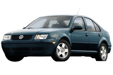
Fuse and relay allocations, as well as circuit ratings, may vary depending on the vehicle's model year, engine variant, and trim package.
Passenger Compartment
Main Fuse Box
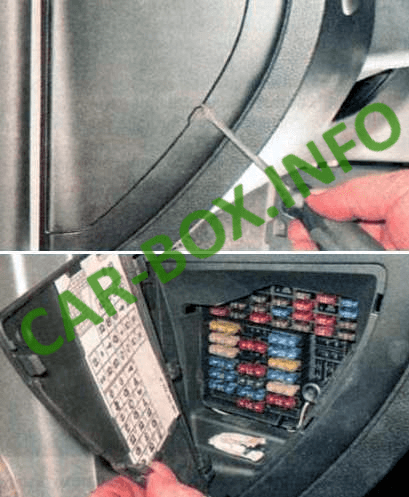
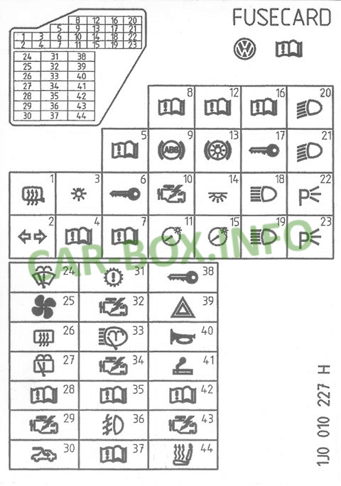
Located on the left end of the dashboard behind a protective access panel. A fuse designation diagram and fuse puller are attached to the inside of the cover.
| Diagram | |
|---|---|
|
|
| No. | Rating / Protected Circuit |
| F1 | 10 A Glove box light, heated power mirrors |
| F2 | 10 A Turn signals, hazard warning lights, headlight range control |
| F3 | 5 A Fog light relay, instrument cluster dimmer switch |
| F4 | 5 A License plate lights |
| F5 | 7.5 A Air conditioning system, Engine Control Unit (ECU), power mirrors, heated seats |
| F6 | 5 A Central locking system, power windows |
| F7 | 10 A Reverse lights |
| F9 | 5 A ABS, Electronic Stability Program (ESP), Traction Control System (ASR) |
| F10 | 15 A Engine Control Unit (ECU) |
| F11 | 5 A Instrument cluster |
| F12 | 7.5 A Data Link Connector (OBD-II port power supply) |
| F13 | 10 A Brake lights |
| F14 | 10 A Interior lighting, central locking system |
| F15 | 5 A Instrument cluster, ESP / ASR control module |
| F18 | 10 A Right headlight (high beam) |
| F19 | 10 A Left headlight (high beam) |
| F20 | 15 A Right headlight (low beam), HID/Xenon leveling control unit |
| F21 | 15 A Left headlight (low beam), HID/Xenon leveling control unit |
| F22 | 5 A Right parking light / side marker light |
| F23 | 5 A Left parking light / side marker light |
| F24 | 20 A Windshield wiper motor, windshield washer pump |
| F25 | 25 A HVAC blower motor, air conditioning blower |
| F26 | 25 A Heated rear window (defroster) |
| F27 | 15 A Rear window wiper motor (Wagon models) |
| F28 | 15 A Fuel pump |
| F29 | 15 A Engine Management System (ECU), ignition system |
| F31 | 20 A Automatic Transmission Control Module (TCM) |
| F32 | 10 A Fuel injectors |
| F34 | 10 A Engine management system components |
| F35 | 30 A 12 V power outlet / trailer socket |
| F36 | 15 A Front fog lights |
| F37 | 10 A Audio system, central convenience control module |
| F38 | 15 A Luggage compartment light, central locking, fuel filler door release |
| F39 | 15 A Emergency flasher, anti-theft alarm system |
| F40 | 20 A Dual-tone horn |
| F41 | 15 A Cigarette lighter / power socket fuse |
| F42 | 15 A Audio system / radio unit |
| F43 | 10 A Engine management system sensors and actuators |
| F44 | 15 A Heated seats |
Relay Panel
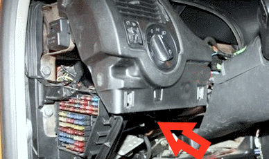
The main relay panel is located beneath the lower dashboard on the driver's side.
| Diagram | |
|---|---|

|
|
| No. | Description |
| 1 | Main relay carrier; |
| 2 | Auxiliary relay carrier; |
| K1 | Horn relay; |
| K2 | X-contact load reduction relay (Terminal 75); |
| K4 | Fuel pump relay; |
| K5 | Wiper intermittent control module; |
| K5 | Front passenger seat heating control unit; |
| K6 | Driver seat heating control unit; |
| K7 | Brake light switch cutout / cruise control relay; |
| K8 | Cigarette lighter relay; |
| K11 | Starter interlock & reverse light relay (automatic transmission); |
| S37 | Power window thermal circuit breaker / fuse; |
| S111 | Anti-theft alarm system fuse; |
| S114 | Anti-theft horn fuse. |
Engine Compartment
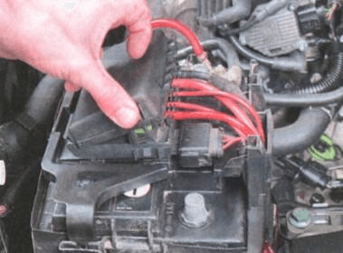
The engine compartment fuse box is mounted directly on top of the battery cover.

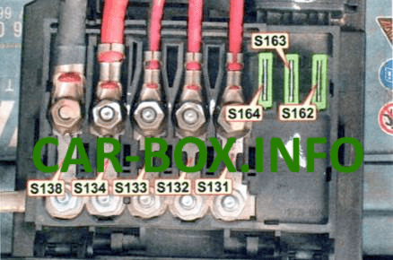
It consists of a blade fuse panel and high-current strip fuses.
| Diagram | |
|---|---|
|
|
| No. | Rating / Protected Circuit |
| S131 | 50 A Secondary air injection (SAI) pump |
| S132 | 50 A Engine Control Unit (ECU) main power supply |
| S133 | 40 A / 50 A Radiator cooling fan motor |
| S134 | 110 A Interior power feed (Terminal 30) |
| S138 | 110 A / 150 A Generator (alternator) B+ cable |
| S162 | 30 A ABS hydraulic pump |
| S163 | 30 A ABS valves |
| S164 | 30 A Radiator cooling fan motor (low speed) |
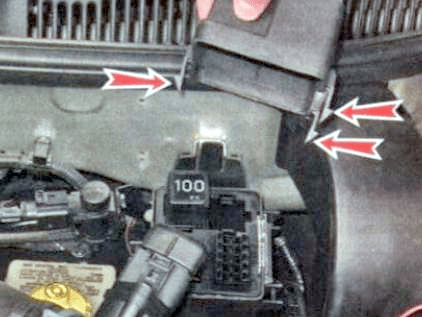
An auxiliary relay box is located under the hood on the plenum chamber bulkhead. Depending on engine configuration, it houses relays for the secondary air injection pump or diesel glow plug system. Note: The turn signal and hazard flasher relay is integrated directly into the hazard switch on the dashboard, while the radiator cooling fan control unit (FCU) is mounted on the left longitudinal frame rail below the battery.
