
The Golf is a compact family car manufactured by the German automaker VW. The eighth generation was introduced in October 2019 and arrived in German showrooms in December 2019. In this manual, we will provide a detailed breakdown of the fuse box diagrams for the Volkswagen Golf (eighth generation; body codes CD1 for the hatchback and CG5 for the Variant/Wagon/Estate; MQB Evo platform) for the 2019, 2020, 2021, 2022, 2023, 2024, 2025, 2026, 2027, and 2028 model years.
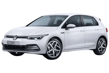
Here you will find the locations and photos of the power distribution boxes. We will specifically highlight the fuses responsible for the cigarette lighter and the fuel pump.
Passenger Compartment
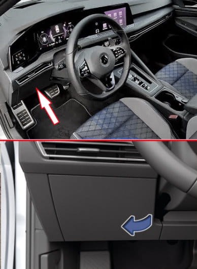
LHD: The main interior fuse and relay box is located on the driver's side, behind the glove compartment.
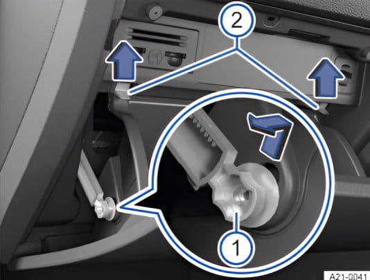
RHD: The fuse box located behind the glove compartment on the passenger side.
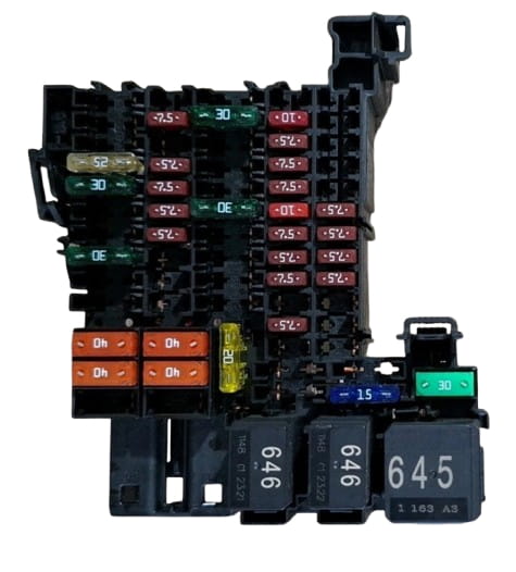
Example photo.
| Diagram | ||
|---|---|---|
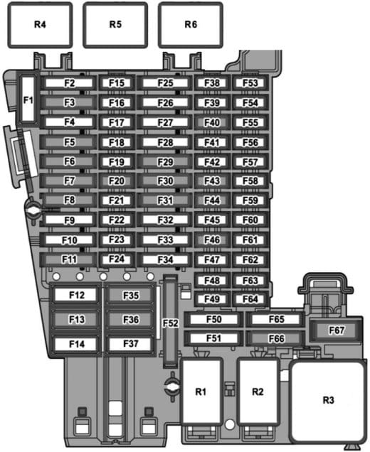
|
||
| No. | Protected circuit | Amperage (A) |
| SC1 | Reserved | — |
| SC2 | Reserved | — |
| SC3 | Trailer recognition control module | 25 |
| SC4 | AdBlue heater control module (diesel) | 20 |
| SC5 | Automatic transmission selector lever lock motor (parking lock) | 25 |
| SC6 | Body Control Module (BCM): interior lighting | 30 |
| SC7 | Climate control module: seat heating | 30 |
| SC8 | Sunroof control module | 20 |
| SC9 | Door control modules (driver/passenger), rear power windows | 30 |
| SC10 | Reserved | — |
| SC11 | Trailer recognition control module | 15 |
| SC12 | Body Control Module (BCM): exterior lighting (left side) | 40 |
| SC13 | Body Control Module (BCM): central locking | 40 |
| SC14 | Audio system amplifier (Digital Sound Package) | 30 |
| SC15 | Reserved | — |
| SC16 | Airbag control module | 7.5 |
| SC17 | AdBlue dosing system relay | 10 |
| SC18 | Keyless entry and start system interface, door handles, anti-theft modules, electronic steering column lock | 7.5 |
| SC19 | Instrument cluster, emergency call system module | 7.5 |
| SC20 | Internet access module, USB port, phone mount, TV tuner (Japanese market) | 7.5 |
| SC21 | Blind spot monitoring modules, exterior mirrors, tailgate handle | 7.5 |
| SC22 | Reserved | — |
| SC23 | Reserved | — |
| SC24 | All-Wheel Drive (AWD) control module | 15 |
| SC25 | Front seat belt pretensioner | 25 |
| SC26 | Door and power window control modules | 30 |
| SC27 | Front seat belt pretensioner | 25 |
| SC28 | Reserved | — |
| SC29 | Trailer recognition control module | 15 |
| SC30 | Infotainment system electronic module | 30 |
| SC31 | Trailer recognition control module | 25 |
| SC32 | Rear climate control module, rear seat heating | 25 |
| SC33 | Reserved | — |
| SC34 | Reserved | — |
| SC35 | Body Control Module (BCM): exterior lighting (right side) | 40 |
| SC36 | HVAC blower motor control module | 40 |
| SC37 | Reserved | — |
| SC38 | Reserved | — |
| SC39 | Steering column electronics module | 10 |
| SC40 | Factory anti-theft alarm siren | 7.5 |
| SC41 | Data bus diagnostic interface (Gateway) | 7.5 |
| SC42 | Automatic transmission selector, selector position indicator | 7.5 |
| SC43 | Interior temperature sensor, climate control module, rear window defogger relay | 10 |
| SC44 | Electromechanical parking brake switch, diagnostic connector (OBD-II), roof module, interior motion sensor, rain and light sensor | 7.5 |
| SC45 | Steering column electronics module | 7.5 |
| SC46 | Head-Up Display (HUD) control module | 7.5 |
| SC47 | Adaptive Chassis Control (DCC) module | 10 |
| SC48 | USB charging port | 7.5 |
| SC49 | Reserved | — |
| SC50 | Reserved | — |
| SC51 | Reserved | — |
| SC52 | 12V power outlet, cigarette lighter | 20 |
| SC53 | Reserved | — |
| SC54 | Reserved | — |
| SC55 | Reserved | — |
| SC56 | Reserved | — |
| SC57 | Reserved | — |
| SC58 | Front driver assistance camera, park assist control module, adaptive cruise control radar | 7.5 |
| SC59 | Electromechanical parking brake switch, auto-dimming rearview mirror, air quality sensor | 7.5 |
| SC60 | Diagnostic connector (OBD-II) | 7.5 |
| SC61 | Starter relay 1 and 2 | 7.5 |
| SC62 | Reserved | — |
| SC63 | Reserved | — |
| SC64 | Reserved | — |
| SC65 | Engine sound generator control module | 10 |
| SC66 | Rear wiper motor | 15 |
| SC67 | Rear window defogger relay | 30 |
| R1 | 12V power outlet relay | — |
| R2 | Terminal 15 (ignition) power supply relay | — |
| R3 | Rear window defogger relay | — |
| R4 | AdBlue dosing system relay (diesel) | — |
| R5 | Reserved | — |
| R6 | Reserved | — |
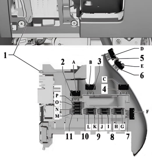
Adjacent to the main box is a panel with individual fuses.
| Diagram | ||
|---|---|---|
|
||
| No. | Function | Amperage (A) |
| A | Driver seat adjustment control module | 15 |
| B | Reserved | — |
| C | Reserved | — |
| D | Driver seat backrest and cushion fans, front left seat adjustment control module | 15 |
| E | Passenger seat backrest and cushion fans, front right seat adjustment control module | 15 |
| F | Reserved | — |
| G | Special purpose vehicle control module, diagnostic connector 2, connection points (wheelchair lift, two-way radio, event data recorder, emergency beacons) | 10 |
| H | Reserved | — |
| I | Reserved | — |
| J | Reserved | — |
| K | Wheelchair lift connection point, special purpose vehicle control module | 40 |
| L | Special purpose vehicle control module, fuse 16 on the SRSH relay and fuse holder | 40 |
| M | Reserved | — |
| N | Reserved | — |
| O | Reserved | — |
| P | Reserved | — |
Engine Compartment
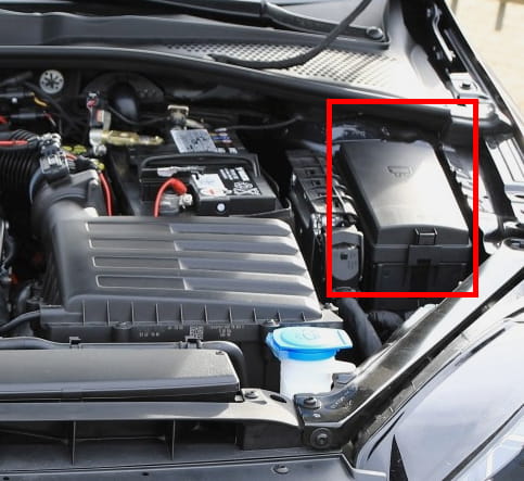
The main fuse and relay box under the hood is located behind a protective cover next to the battery.
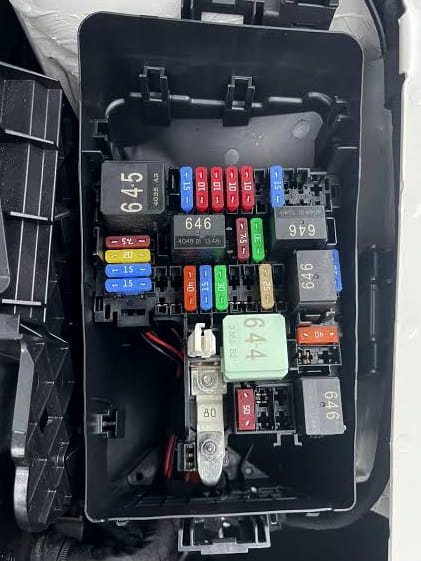
General view.
| Diagram | ||
|---|---|---|

|
||
| No. | Protected circuit | Amperage (A) |
| SB1 | Electromechanical power steering control module | 400 |
| SB2 | Main relay (petrol) / Terminal 30 power supply relay (diesel), engine control module, ABS control module | 7.5 |
| SB3 | Engine components power supply relay (2.0L petrol) | 20 |
| SB3 | Gas shut-off valve relay (CNG engine) | 7.5 |
| SB4 | Left headlight | 15 |
| SB5 | Right headlight | 15 |
| SB6 | Reserved | — |
| SB7 | Auxiliary transmission fluid hydraulic pump 1 | 30 |
| SB8 | Electromechanical brake booster | 40 |
| SB9 | Horn relay | 15 |
| SB10 | Windshield wiper motor control module | 30 |
| SB11 | Reserved | — |
| SB12 | Dual-clutch transmission Mechatronic unit, automatic transmission control module | 15 / 30 |
| SB13 | Hydraulic brake system control module (ABS) | 25 |
| SB14 | Auxiliary parking heater control module | 20 |
| SB15 | Hydraulic brake system control module (ABS) | 40 |
| SB16 | Reserved | — |
| SB17 | Auxiliary air heater element (diesel) | 40 |
| SB18 | Auxiliary air heater element (diesel) | 40 |
| SB19 | Reserved | — |
| SB20 | Differential lock control module | 15 |
| SB21 | Engine control module | 7.5 |
| SB22 | Starter motor | 30 |
| SB23 | Engine control module | 15 |
| SB24 | Radiator fan, oil level and temperature sensor, EVAP canister purge valve, camshaft control valves, oil pressure control valve, piston cooling valve, fuel metering valve (diesel), AdBlue dosing system relay, glow plug control module, starter-generator (48V), fuel tank gas pressure sensor | 7.5 / 10 |
| SB25 | Gas injectors 1–4 (CNG engine) | 10 |
| SB26 | Crankcase ventilation heater, oil pressure control valve, thermostat actuator, coolant control valve, piston cooling valve, coolant circulation pump, charge air cooling pump, auxiliary heater pump | 10 |
| SB27 | Particulate filter sensor, oxygen sensors (upstream and downstream of catalytic converter), NOx sensor control modules | 10 / 15 |
| SB28 | Ignition coils 1–4, EVAP canister purge valve, variable valve timing control valves, oil pressure control valve | 20 |
| SB29 | Fuel pump control module | 15 / 20 |
| SB30 | Reserved | — |
| SB31 | Reserved | — |
| SB32 | Reserved | — |
| R1 | Main relay | — |
| R2 | High-output electric heater relay (diesel) | — |
| R3 | Horn relay | — |
| R4 | Starter relay 1 | — |
| R5 | Starter relay 2 | — |
| R6 | Gas shut-off valve relay (CNG), engine components power supply relay | — |
| R7 | Glow plug control module (diesel) | — |
| R8 | Low-output electric heater relay | — |
High-amp fusible links are located near the positive battery terminal.
| Diagram | ||
|---|---|---|

|
||
| No. | Function | Amperage (A) |
| SA1 | Main power supply feed for the fuse panel (engine compartment) | 150 |
| SA2 | Radiator cooling fan | 50 |
| SA3 | Reserved | — |
| SA4 | Main power supply feed for the fuse panel (passenger compartment) | 125 |
| SA5 | Main power supply feed for the fuse panel (passenger compartment) | 125 |
| 508 | Jump-start terminal / Positive battery terminal connection | — |
