The 6th generation Volkswagen Golf compact car was produced with hatchback, station wagon and convertible bodies in 2008, 2009, 2010, 2011, 2012 and 2013. Our material will provide a description of the Volkswagen Golf 6 fuse boxes and relays with diagrams and photo examples. Let's separate out the fuse responsible for the cigarette lighter.
In the engine compartment
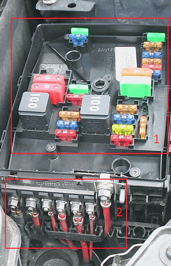
Located on the left side of the insides and is covered with a protective cover. Consists of two parts: 1 - main box and 2 - high power box.
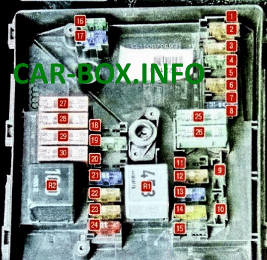
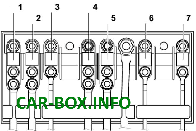
Main fuse box
Diagram.
|
|
| № | (Amps) Description |
| R1 | ECU System Relay / Fan Relay |
| R2 | Air blower pump relay / Automatic gearbox control relay |
| 1 | (30A) Wiper motor |
| 2 | (30A) Gearbox mechatronic unit |
| 3 | (20A) Onboard supply control unit |
| 4 | (20A) ABS control module |
| 5 | (15A) Transmission control module (ECM) |
| 6 | (5A) Instrument panel, Steering column control module |
| 7 | (40A) Power supply relay cl. 15 |
| 8 | (15A) Audio system, Head unit (25A) Voltage stabilizer |
| 9 | (5A) Telephone control unit |
| 10 | (5A / 10A) Electronic engine control unit, Motronic power relay |
| 11 | (20A) Auxiliary heater control unit, auxiliary heater relay |
| 12 | (5A) CAN data bus, gateway control unit |
| 13 | (15A / 30A) Electronic engine control unit |
| 14 | (20A) Fuel booster pump, Ignition |
| 15 | (5A / 10A) Glow plug relay, Fuel pump relay, Lambda probe |
| 16 | (30A) Lamps and headlights - right side |
| 17 | (15A) Horn |
| 18 | (30A) Audio system, amplifier |
| 19 | (30A) Windshield wiper / washer |
| 20 | (10A) Coolant circulation pump (20A) Fuel pressure regulating valve |
| 21 | (10A / 15A) Lambda probe heater, Central locking motor in front passenger door (20A) Brake vacuum pump |
| 22 | (5A) Clutch pedal position switch |
| 23 | (5A / 10A / 15A) Engine management system |
| 24 | (10A) Engine management system (pump relay, injectors, etc.) |
| 25 | (40A) ABS control unit |
| 26 | (30A) Bulbs and headlights - left side, onboard supply control unit |
| 27 | (40 / 50A) Glow plug control unit, Secondary air pump motor |
| 28 | (30A) Terminal 15 power supply relay 2 |
| 29 | (50A) Thermal fuse 1 for driver's seat adjustment |
| 30 | (50A) Contact relief relay X |
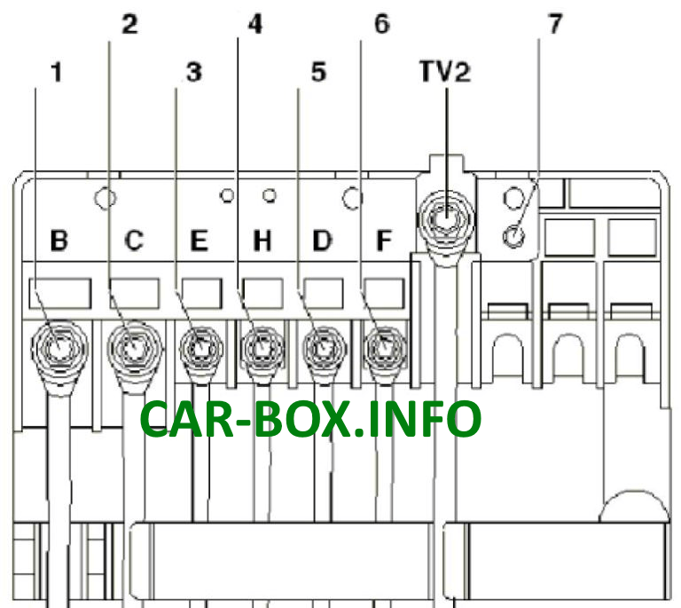
High power box
Diagram.
| Type 1 | |
|
|
| 1 | 150A / 200A - Generator |
| 2 | 80A - Power steering control unit |
| 3 | 50A - Radiator fan and its control unit |
| 4 | 80A - Heating relay or Additional equipment |
| 5 | 80A - Terminal 30, passenger compartment fuse box |
| 6 | 40A - Low power heating relay |
| 7 | 30/40 / 50А - Reserve |
| Type 2 | |
|
|
| 1 | 150A / 200A - Generator |
| 2 | 80A - Power steering unit |
| 3 | 50A - Radiator fan and its control unit |
| 4 | 80A - Reserve |
| 5 | 80A - Terminal 30, passenger compartment fuse box |
| 6 | Reserve |
| 7 | Reserve |
In the passenger compartment
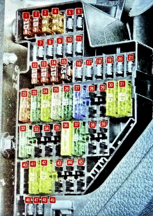
Fuse box

Located at the end of the dashboard on the driver's side, behind the protective cover.
| Diagram | |
|---|---|
|
|
| № | (Amps) Legend |
| F1 | (10A) DLC connector, Engine control unit, Relay for auxiliary heater operation, Dimmer for switches and instrument cluster, Headlight range control, Adaptive cruise control unit, Brake light switch |
| F2 | (5A) ABS, ESP, Instrument cluster control unit, Engine control unit, Starter relay, Power steering control unit, Trailer detection control unit |
| F3 | (5A) Airbag control module |
| F4 | (5A) Oil level and temperature sensor, High pressure sensor, Engine oil level and temperature sensor, ASR and ESP deactivation button, Tire pressure indicator button, Airbag control unit |
| F5 | (10A) Left headlight control module |
| F6 | (10A) Right headlight control module |
| F7 | Reserve |
| F8 | Reserve |
| F9 | Reserve |
| F10 | Reserve |
| F11 | Reserve |
| F12 | (10A) Door control module (driver), door control module (passenger), central locking |
| F13 | (10A) Diagnostic socket, light switch, rain and light sensor, fog lamp switch |
| F14 | (10A) Brake light switch (brake pedal position sensor), automatic gearbox control unit, Climatronic control unit |
| F15 | (20A) Button for unlocking the door / tailgate handle, Onboard supply control unit, Central locking |
| F16 | (10A) Rear view camera |
| F17 | (5 / 10A) Audio system, tilt sensor, alarm siren, signal relay |
| F18 | Reserve |
| F19 | (5A) Crash data logger, Engine speed limiter control unit |
| F20 | (20A) Entry and start authorization control module, voltage stabilizer |
| F21 | (10A) Electronic steering column lock control module |
| F22 | (40A) Supply fan |
| F23 | (30A) Power windows, door control module |
| F24 | (20A) Onboard supply control unit |
| F25 | (25A) Multifunction control module (rear window heater, air conditioner control unit, heater and operating mode selection switch) |
| F26 | (30A) Rear door control module and glass lifters |
| F27 | (15A) Engine management (fuel pump) |
| F28 | (15A) Voltage stabilizer, Head unit |
| F29 | Reserve |
| F30 | (20A) Automatic transmission control module |
| F31 | (20A) Brake vacuum pump |
| F32 | (30A) Inverter with socket, 12 V - 230 V |
| F33 | (25A) Sunroof |
| F34 | (15A) Power seats |
| F35 | (10A) Electronic damping control module |
| F36 | (20A) Headlamp washers |
| F37 | (30A) Heated seats |
| F38 | (20A) Horn relay, anti-theft alarm, convenience system central control unit |
| F39 | - |
| F40 | (40A) Heater / air conditioner |
| F41 | (15A) Glass cleaner motor |
| F42 | (20A) Cigarette lighter, 12V socket |
| F43 | (15A) Trailer control module |
| F44 | (20A) Trailer control module |
| F45 | (15A) Trailer control module |
| F46 | Reserve |
| F47 | (5A) Instrument cluster control module |
| F48 | (5A) Mobile phone control electronics control unit, Voltage stabilizer, Magnetic field sensor for compass |
| F49 | Reserve |
| The fuse number 42, 20A, is responsible for the cigarette lighter. | |
Relay box
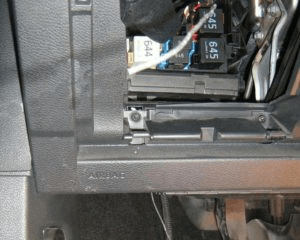
It is located under the dashboard itself, behind the trim.
Upper relay block diagram
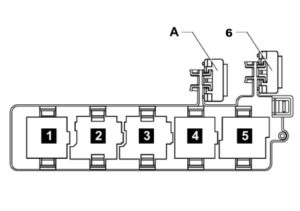
- Terminal + ignition lock relay
- Horn relay
- Headlight washer relay
- Power circuit unloading relay
- Relay for electric window heating
- or A - 30A Thermal fuse 1 for adjusting the position of the driver's seat
General description of the functions performed by the onboard power supply control unit: Control of relay circuits, Control of lighting devices, Power distribution between consumers, Control of windshield wipers (via LIN), Control of rain and light sensors, Turning on the sound signal, Control of heated windows, windscreen and rear, Saving personal settings , Management of the interior monitoring system, tilt sensors and burglar alarms, Convenient locking / unlocking, Remote control (built-in antenna), Central locking (control of locks, doors, hatches and covers), Tire pressure monitoring system (separate logic module with a diagnostic address) , Control of door control units, Lighting for traffic in the daytime, Static adaptive lighting system.

interesting. thanks