Volkswagen Golf 5 th generation was produced in 2003, 2004, 2005, 2006, 2007, 2008 and 2009 mainly in the hatchback, with both petrol and diesel engines. In our material you will find a description of the Golf 5 fuse boxes and relays with diagrams and photographs. We will show the location of all electronic control units. The fuse responsible for the “Cigarette lighter” is highlighted in bold. This material will also be useful to the owner of Volkswagen Jetta 5 cars, since these models have a similar electrical circuit.
General layout
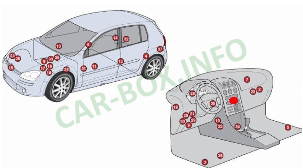
General diagram of electronic control units.
|
|
| № | Сontrol unit |
| 1 | Air conditioner electronic control unit |
| 2 | Air conditioning / heater fan motor control unit |
| 3 | Side impact sensor, driver's side |
| 4 | Side impact sensor, rear left |
| 5 | Side impact sensor, passenger side |
| 6 | Side impact sensor, rear right |
| 7 | Vehicle tilt sensor (anti-theft system) |
| 8 | Accumulator battery |
| 9 | Diagnostic connector (DLC) |
| 10 | Data bus connector |
| 11 | Driver's door control unit - in the door |
| 12 | Rear left door electrical control unit |
| 13 | Control unit for electrical equipment of the passenger door - in the door |
| 14 | Rear right door electrical control unit |
| 15 | Cooling fan motor control unit - on the cooling fan motor |
| 16 | Fuse / relay box, engine compartment 1 |
| 17 | Fuse / relay box, engine compartment 2 |
| 18 | Fuse / relay box, engine compartment 3 - under engine fuse / relay box 1 |
| 19 | Fuse / relay box, instrument cluster 1 |
| 20 | Fuse / relay box, instrument panel 2 |
| 21 | Fuse / relay box, instrument cluster 3 |
| 22 | Headlight range control unit (models with xenon headlights |
| 23 | Heater blower motor resistor |
| 24 | Horn 1 |
| 25 | Horn 2 |
| 28 | Instrument cluster control unit |
| 29 | Multifunction control unit 1 - in the dashboard fuse / relay box 3 - functions: Cigarette lighter, cruise control, fog lights, hazard warning lights, headlights, rear window defogger, horn, interior lamps, rear window wiper / washer, reversing lights , front marker lamps, brake lights, windshield washer, windshield wiper |
| 30 | Multifunctional control unit 2 - functions: Anti-theft system, boot lid / tailgate lock, tailgate / tailgate opener, central locking, power door mirrors, power windows, drive for opening the fuel filler flap, sunroof |
| 31 | NOx sensor control unit - under the body |
| 32 | Parking system control unit - luggage compartment right |
| 33 | Power steering control unit - above the steering rack |
| 34 | Electronic control unit SRS |
| 35 | Steering column electronics control unit |
| 36 | Telephone control unit - under the seat, if fitted |
| 37 | Trailer control unit - left luggage compartment |
| 38 | Electronic gearbox control unit - behind the wheel arch |
| 39 | Windshield wiper control unit - on the resonator of the intake system |
In the engine compartment
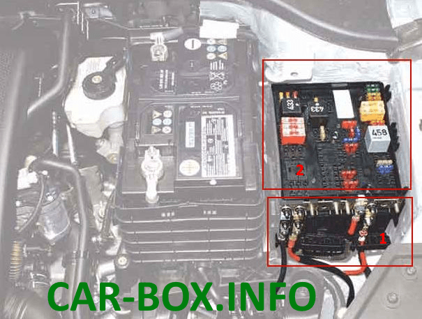
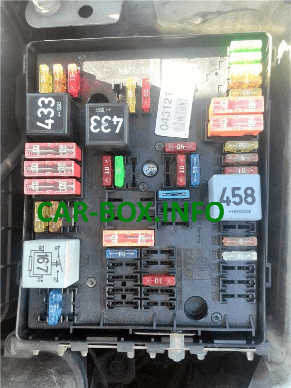
Located next to the battery and is covered by a protective cover. Consists of two blocks. 1 - Department of high power fuses in the form of fusible links. 2 - section main of fuses and relays.
Fuse box
Type 1
General view.
| Diagram | |
|---|---|
|
|
| № | (Amps) Legend |
| 1 | Engine control relay |
| 2 | Outlet air pump relay |
| F1 | (30A) Windscreen wiper |
| F2 | (5A) Steering column electronics control module / (30A) DSG gearbox mechatronic unit |
| F3 | (5A) Onboard supply control unit |
| F4 | (30A) ABS control module |
| F5 | (15A) Gearbox control module |
| F6 | (5A) Instrument cluster |
| F7 | (40A) Power relay |
| F8 | (15A) Audio system / Head unit |
| F9 | (5A) Telephone control unit |
| F10 | (5A / 10A) Electronic engine control unit |
| F11 | (20A) Auxiliary heater control unit |
| F12 | (5A) CAN data bus, gateway control unit |
| F13 | (15A / 30A) Electronic engine control unit |
| F14 | (20A) Engine management system, ignition coil |
| F15 | (5A / 10A) Engine management system, Lambda probe |
| F16 | (30A) ABS control module, headlight right |
| F17 | (15A) Horn |
| F18 | (30A) Audio system |
| F19 | (30A) Windshield wiper / washer |
| F20 | (10A) Coolant pump |
| F21 | (10A / 15A) Engine management system, Lambda probe, Electromagnetic clutch, drive blower |
| F22 | (5A) Clutch pedal position switch |
| F23 | (5A / 10A / 15A) Engine management system, Fuel pressure regulator, Secondary air pump relay |
| F24 | (10A) Engine management system, Exhaust gas recirculation valve, Solenoid valve |
| F25 | (40A) ABS control unit |
| F26 | (30A) LH headlamp |
| F27 | (50A) Glow plug control module |
| F28 | (40A) Main ignition circuits |
| F29 | (50A) Thermal fuse 1 for seat adjustment |
| F30 | (40A) Starting system (50A) Relay for unloading contact X |
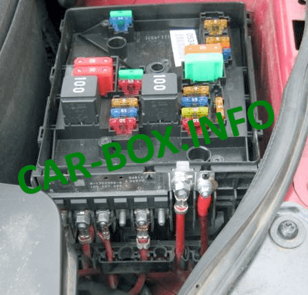
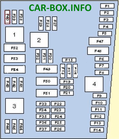
Type 2
General view.
| Diagram | |
|---|---|
|
|
| № | (Amps) Description |
| 1 | Relay 2 main ignition circuits |
| 2 | Starter relay |
| 3 | Fuel pump relay - 1.4 (BCA) / 1.6 (BGU) |
| 4 | Relay 1 of the main ignition circuits |
| F1 | (30A) ABS |
| F2 | (30A) ABS |
| F3 | (20A) Multifunction control module 2 |
| F4 | (5A) Multifunction control module 1 |
| F5 | (20A) Horn |
| F6 | (5A / 20A) Engine management |
| F7 | (5A) Brake light switch (brake pedal position sensor), clutch pedal position sensor |
| F8 | (10A) Cooling fan motor control module, engine management |
| F9 | (10A) Engine management |
| F10 | (10A) Engine management |
| F11 | (25A) Engine management - petrol |
| F12 | (15A) Engine management |
| F13 | (20A) Automatic transmission |
| F14 | - |
| F15 | (40A) Starter |
| F16 | (15A) Steering column electronics control module |
| F17 | (10A) Instrument panel |
| F18 | - |
| F19 | (15A) Audio system, navigation system |
| F20 | (10A) Telephone |
| F21 | - |
| F22 | - |
| F23 | (10A) Cruise control system |
| F24 | (10A) Data bus connector |
| F25 | - |
| F26 | (5A) Engine management - Diesel |
| F27 | (10A) Crankcase ventilation heater |
| F28 | (20A) Automatic transmission |
| F29 | (20A) Engine management |
| F30 | (20A) Heater / air conditioner |
| F31 | (25A) Windshield wiper |
| F32 | (10A) Engine management |
| F33 | (15A) Fuel booster pump |
| F34 | - |
| F35 | - |
| F36 | - |
| F37 | - |
| F38 | (10A) Headlight range control |
| F39 | (5A) Engine oil temperature sensor, instrument cluster |
| F40 | (20A) Dashboard fuse / relay box 1 (F1-F11 / F29-F31) |
| F41 | - |
| F42 | (5A) Engine management - Petrol |
| F43 | - |
| F44 | - |
| F45 | - |
| F46 | - |
| F47 | (40A) Multifunction control module 1 |
| F48 | (40A) Multifunction control module 1 |
| F49 | (50A) Multifunction control module 1 |
| F50 | (40A) Audio system |
| F51 | (50A) Glow plug control module |
| F52 | (50A) Multifunction control module 1 |
| F53 | (50A) Dashboard fuse / relay box 1 (P32-B37), Dashboard fuse / relay box 2 (F4) |
| F54 | - |
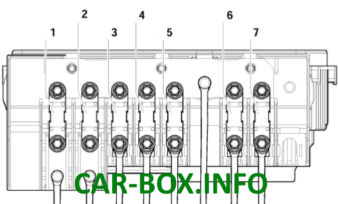
High power fusible links
Diagram.
| № | Amps - Description |
| Type 1 | |
|
|
| 1 | 150A / 200A - Generator |
| 2 | 80A - Power steering control unit |
| 3 | 50A - Radiator fan and its control unit |
| 4 | 40A - Relay of low power heating or Additional equipment |
| 5 | 100A - Fuses in the cabin |
| 6 | 80A - Fuses in the cabin, 100A - optional |
| 7 | 30/40 / 50А - Trailer connection and additional equipment |
| Type 2 | |

|
|
| 1 | 150A / 200A - Generator |
| 2 | 80A - Power steering unit |
| 3 | 50A - Radiator fan and its control unit |
| 4 | 40A - Fuses in the cabin |
| 5 | 100A - Fuses in the cabin, 80A - additional equipment |
| 6 | 80A - Fuses in the cabin, 100A - optional |
| 7 | 50A - Reserve |
In some models, additional relays may be located outside the unit: the glow plug control relay and the air pump relay.
In the passenger compartment
Fuse box
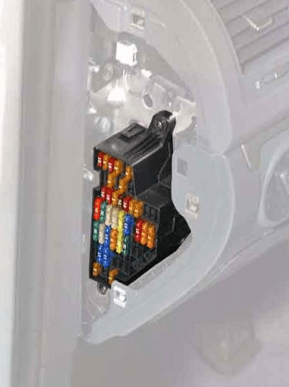
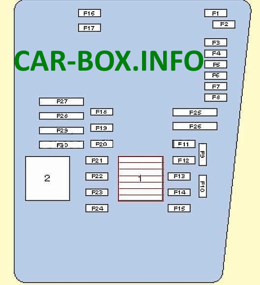
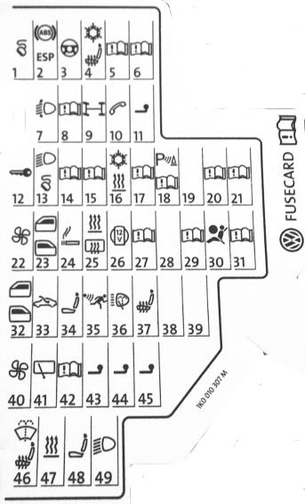
It is located at the end of the dashboard on the driver's side behind the protective cover.
| Diagram | |
|---|---|
|
|
| № | (Amps) Description |
| F1 | (10A) Diagnostic connector DLC, Engine control unit, Relay for auxiliary heater operation |
| F2 | (5A) ABS, ESP |
| F3 | (10A) Power steering, (5A) airbag control module |
| F4 | (5A) Heated seats, heater / air conditioning, air conditioning control unit, oil level and temperature sensor, reversing light |
| F5 | (5A) Brake light switch (brake pedal position sensor), clutch pedal position sensor, control unit for adaptive lighting and headlight range control, on the right headlight |
| F6 | (5A) Data bus connector, engine management, control unit in instrument cluster, control unit for adaptive lighting and headlight range control, on the left headlight |
| F7 | (5A) Headlamp leveling control module, interior mirror |
| F8 | (5A) Interior rearview mirror, (10A) - Trailer control unit |
| F9 | (5A) 4WD electronic control unit, navigation system |
| F10 | (5A) Telephone, seat occupied detection unit |
| F11 | (5A) Trailer control module |
| F12 | (10A) Door control module (driver), door control module (passenger), central locking |
| F13 | (10A) Diagnostic socket, light switch, rain and light sensor |
| F14 | (5A) Brake light switch (brake pedal position sensor), automatic transmission control unit, ABS control unit |
| F15 | (7.5A) Multifunction control module (interior lighting) |
| F16 | (10A) Heater / air conditioner, antenna selection control unit |
| F17 | (5A) Audio system, rain sensor (windshield wiper), anti-theft alarm horn |
| F18 | (5A) Parking control module, selector lever position sensor |
| F19 | (5A) Emergency data logger |
| F20 | (5A) Anti-lock braking system |
| F21 | (5A) Control unit for maximum engine speed limitation, front left footwell (special vehicles) |
| F22 | (40A) Supply fan |
| F23 | (30A) Power windows, door control module |
| F24 | (25A) Cigarette lighter fuse, front and rear, convenience system central control unit |
| F25 | (25A) Multifunction control module (rear window heater, air conditioner control unit, heater and operating mode selection switch) |
| F26 | (20A) Charging connector (socket) (25A) Rear door control unit |
| F27 | (15A) Engine management (fuel pump) |
| F28 | (25A) Inverter with socket for special vehicles |
| F29 | (10A) Engine management |
| F30 | (5A) Airbag (10A) Injectors (20A) automatic gearbox control unit |
| F31 | (5A) Reversing lights (20A) Brake vacuum pump |
| F32 | (15A) Power windows |
| F33 | (25A) Sunroof |
| F34 | (15A) Power seats |
| F35 | (5A) Anti-theft system |
| F36 | (20A) Headlamp washers |
| F37 | (30A) Heated seats |
| F38 | (20A) Horn relay, anti-theft alarm, convenience system central control unit |
| F39 | - |
| F40 | (40A) Heater / air conditioner |
| F41 | (15 / 20A) Rear window cleaner / washer |
| F42 | (15 / 20A) Windshield washer, Cigarette lighter |
| F43 | (15A) Trailer control module |
| F44 | (20A) Trailer control module |
| F45 | (15A) Trailer control module |
| F46 | (5A) Air conditioning / heating system, heater and windshield washer nozzles |
| F47 | (5A) Heater / air conditioner |
| F48 | (7.5A) Power Seat, Steering Column Adjustment Drive, Mag-Lite Flashlight and Walkie Talkie Charger |
| F49 | (7.5) Light switch |
| Depending on the configuration and year of manufacture, fuses 24 or 42 are responsible for the cigarette lighter. | |
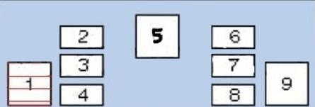
Relay box

Located under the dashboard on the driver's side and consists of 2: main and additional.
| Diagram | |
|---|---|
| № | Description |
| Main one | |
|
|
| 1 | - |
| 2 | Heated mirror relay |
| 3 | - |
| 4 | Relay for multifunction control unit |
| 5 | Heated rear window relay |
| 6 | Relay horn |
| 7 | Windshield washer pump relay 1 |
| 8 | Windshield washer pump relay 2 |
| 9 | Relay for auxiliary ignition circuits |
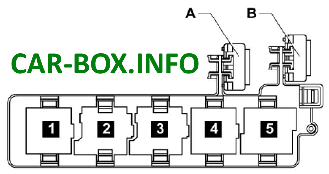
| Additional | |
|
|
| 1 | Headlight washer pump relay |
| 2 | Booster Fuel Pump Relay - Diesel |
| 3 | Starter relay |
| 4 | Headlight washer pump relay |
| 5a | Start relay (fuel system) |
| 5b | Auxiliary heater relay |
| A | 30A Thermo fuse 1 for adjusting the position of the driver's seat |
| B | 30A Thermo Fuse 2 Driver Seat Adjustment |
