The 4th generation Volkswagen Golf belongs to the compact class cars. Produced in 1997, 1998, 1999, 2000, 2001, 2002, 2003 and 2004 with hatchback, station wagon and convertible bodies. In this publication, we will present a description of the Golf 4 fuse block and relay diagrams with a photo - an example. The fuse responsible for the “Cigarette lighter” is highlighted in bold.

Differences in the presented material and your location are possible. Check the actual assignment with the description on the protective cover. If you own a different generation of the vehicle, read the description for the 3rd and 5th generation respectively.
In the passenger compartment
Fuse box
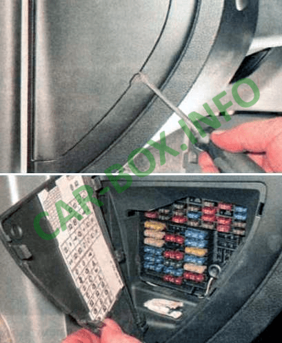
Located at the left end of the dashboard and is covered by a protective cover.
| Diagram | |
|---|---|
|
|
| № | Amps / Description |
| F1 | 10A Glove box lighting lamp, electric heated mirrors |
| F2 | 10A Direction indicators, hazard warning lights, headlight electrocorrector |
| F3 | 5A Fog lamp relay, dimmer |
| F4 | 5A License plate lamps |
| F5 | 7.5A Air conditioning, engine management system, electric mirrors, seat heating |
| F6 | 5A Central locking and power windows |
| F7 | 10A Reversing lamps |
| F9 | 5A ABS, motion stabilization system, traction control system |
| F10 | 15A Electronic control unit (ECU) |
| F11 | 5A Instrument panel |
| F12 | 7.5A Power supply for the diagnostic tool |
| F13 | 10A Brake signal lamps |
| F14 | 10A Interior lamps |
| F15 | 5A Instrument panel, motion stabilization system |
| F18 | 10A Right headlamp (high beam) |
| F19 | 10A Left headlamp (high beam) |
| F20 | 15A Right headlamp (low beam), right headlight (discharge lamp), control of headlights with discharge lamps |
| F21 | 15A Left headlamp (low beam), left headlight (gas discharge lamp) |
| F22 | 5A Side lamp bulb (right headlight) |
| F23 | 5A Side lamp bulb (left headlight) |
| F24 | 20A Windshield wiper motor, windshield washer motor |
| F25 | 25A Electric fan heater, air conditioner |
| F26 | 25A Heated rear window |
| F27 | 15A Tailgate glass wiper motor |
| F28 | 15A Fuel pump |
| F29 | 15A Electronic control unit, ignition |
| F31 | 20A automatic transmission |
| F32 | 10A Injectors |
| F34 | 10A Engine management system |
| F35 | 30A 12V socket |
| F36 | 15A Fog lights |
| F37 | 10A Car radio, comfort system, central locking, power windows |
| F38 | 15A Trunk lamp, central locking, fuel filler flap cover |
| F39 | 15A Alarm |
| F40 | 20A Buzzer |
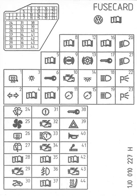
| F41 | 15A Cigarette lighter fuse |
| F42 | 15A Car radio |
| F43 | 10A Engine management system |
| F44 | 15A Heated seats |
| The fuse number 41, 30A, is responsible for the cigarette lighter. | |
Relay box
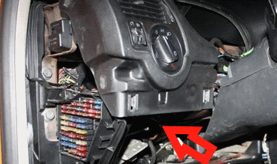
The main unit with the relay is located under the panel itself, on the driver's side.
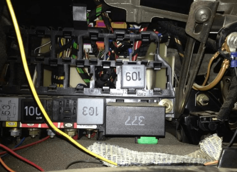
Photo - example
Diagram
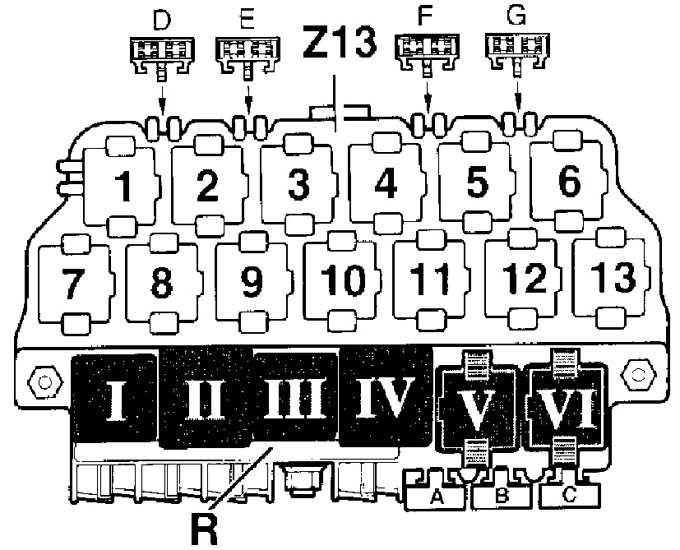
Panel R
- I - Horn relay - Relay 53;
- II - Intermediate relay contact X - Relay 100;
- III - Free;
- IV - Fuel pump relay. Glow plug relay - Relay 409/167/103;
- V - Wiper relay - Relay 603, 377, 389, 192;
- VI - Free;
- A - Fuse for power seat adjustment;
- B - free;
- C - Fuse for power windows, central locking and heated exterior mirrors
Panel Z13
- 1 - Fog lamp relay - Relay 53;
- 2 - Rear door remote unlock relay;
- 3 - Starter lock relay;
- 4 - Free;
- 5 - Free;
- 6 - Radio / telephone distribution relay - Relay 147;
- 7 - Electronic speed control (EPS) relay;
- 8 - External lighting relay;
- 9 - Fuel pump relay (Syncro-diesel) and alarm control unit - TAXI;
- 10 - Alarm control unit - TAXI;
- 11 - Starter & Reverse Lockout Relay - Relay 175;
- 12 - Relay for energizing terminal 30;
- 13 - Radiator fan relay (air conditioning)
Fuses on block Z13
- D - Free;
- E - Rear power window;
- F - Flashing light warning device for theft warning;
- G - Theft warning horn
In the engine compartment
Relay box
An additional relay box is located under the hood on the bulkhead.
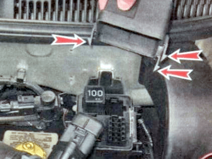
There may be a relay: switching on the secondary air pump or glow plugs. The direction indicator and alarm relay is built into the alarm switch itself. And the control unit for the electric cooling fans is installed on the left side member under the battery.
Box on the battery
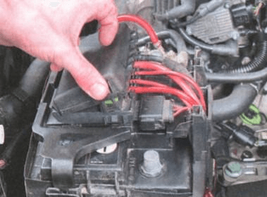
It is located on the battery cover itself.

Consists of a section of fuses and high power fuses.
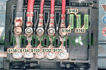
| Diagram | |
|---|---|
|
|
| № | Amps / Legend |
| S131 | 50A Secondary air pump |
| S132 | 50A Engine management system |
| S133 | 40 / 50A Engine cooling fan motor |
| S134 | 110A Electrical equipment |
| S138 | 110 / 150А Output "B +" of the generator |
| S162 | 30A ABS |
| S163 | 30A ABS |
| S164 | 30A Engine cooling fan motor |
