Volkswagen Caravelle and Multivan are very similar both technically and externally. Their main difference between themselves is the interior trim and panels. Both of these models are released on the same base with the wv transporter and represent its passenger version. In this publication you will find a description of the fuse boxes and relays of the Volkswagen Karavella (Multiven) T5. Years of manufacture of the fifth generation (T5): 2002, 2003, 2004, 2005, 2006, 2007, 2008, 2009, 2010, 2011, 2012, 2013, 2014, 2015. We will also show the location of all control units, a video example of finding exactly the fuse and relay blocks, as well as their photos and diagrams. We will pay special attention to the fuses responsible for the cigarette lighter for both generations.

Due to the wide variety of equipment options and the length of the body base, there is no one general description of the purpose of all elements. We will show the most common ones. In case of difficulty, check the designation with yours, on the back of the protective cover or instructions, or contact your nearest dealer.
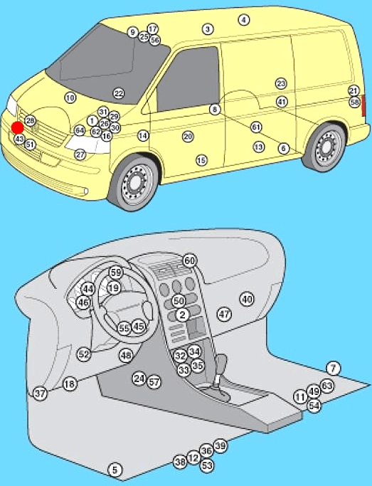
General layout
General arrangement of control units.
|
|
| № | Designation |
| 1 | ABS electronic control unit |
| 2 | Air conditioning control unit - in the heater control panel |
| 3 | Air conditioning control unit (rear) - in the heater control panel |
| 4 | Antenna unit - if available |
| 5 | Side impact sensor, driver's side |
| 6 | Side impact sensor, rear left |
| 7 | Side impact sensor, passenger side |
| 8 | Side impact sensor, rear right |
| 9 | Anti-theft control unit |
| 10 | Anti-theft alarm horn - intake system resonator |
| 11 | Audio Output Amplifier - Under Front Right Seat - If Equipped |
| 12 | Additional battery 1 - under the front left seat - if equipped |
| 13 | Extra Battery 2 (RV) - in the kitchen cabinet |
| 14 | Additional heater control unit (Air Top 3500) - under the body bottom, on the right - if available |
| 15 | Additional heater control unit (Thermo Tor) - under the body bottom, on the left - if any |
| 16 | Accumulator battery |
| 17 | Camping equipment control unit (RV) |
| 18 | Diagnostic connector (DLC) |
| 19 | Diagnostic unit - instrument panel |
| 20 | Driver's door control unit |
| 21 | Rear left door electrical control unit (with electric sliding door) - LH pillar |
| 22 | Passenger door electronics control unit |
| 23 | Rear right door electrical control unit (with electric sliding door) - right pillar |
| 24 | ESP stability control unit (includes acceleration sensor, lateral movement sensor) |
| 25 | Roof lift control unit (RV) |
| 26 | ECM - near engine fuse / relay box 1 |
| 27 | Cooling Fan Motor Control Module 1 - Suspension (Front Left) |
| 28 | Cooling fan motor control unit 2 - in the cooling fan motor 2 - if installed |
| 29 | Fuse / relay box, engine compartment 1 |
| 30 | Fuse / relay box, engine compartment 2 |
| 31 | Fuse / relay box, engine compartment Z |
| 32 | Fuse / Relay Box, Instrument Panel 1 - Center of Instrument Panel |
| 33 | Fuse / relay box 2, dash - under dash fuse / relay box 1 |
| 34 | Fuse / relay box, instrument cluster 3 - behind the fuse / relay box, instrument cluster 1/2 |
| 35 | Fuse / relay box, instrument panel 4 - behind the fuse / relay box, instrument panel 1/2 |
| 36 | Fuse / Relay Box, Left Seat - Under Seat |
| 37 | Additional fuse 1 (differential lock switch, rear 10A) - left front pillar |
| 38 | Additional fuse 2 (additional heater 30A) - under the left seat |
| 39 | Additional fuse 3 (door electronics control unit, left rear 40A) - under the left seat (some models) |
| 40 | Heater blower motor resistor 1 - near the rear heater blower motor |
| 41 | Heater blower motor resistor 2 - near the rear heater blower motor - if equipped |
| 42 | Horn 1 |
| 43 | Sound signal 2 - if available |
| 44 | Immobilizer Control Unit - Instrument Cluster |
| 45 | Immobilizer ring antenna - near the ignition switch |
| 46 | Instrument Cluster Control Unit - Instrument Panel |
| 47 | Telephone control unit - behind the glove box |
| 48 | Multifunction control unit 1 - functions: Automatic transmission (automatic transmission), charging system (with additional battery), cruise control, door / bonnet switch contact recognition, electrical load control, power windows, fuel pump, headlight washers, rear mirror heater door views, rear window defroster, hazard warning lights, windshield defroster, horn, direction indicators, instrument cluster illumination, interior lamps, automatic wipers, reversing lights, starter, sunroof, light switch, windshield washer, wiper windshield |
| 49 | Multifunctional control unit 2 - functions: Anti-theft system, central locking, power door mirrors, power sliding door, power windows, sunroof |
| 50 | Navigation control unit - in navigation display |
| 51 | Ambient temperature sensor |
| 52 | Parking system control unit |
| 53 | Driver's seat heating control unit |
| 54 | Seat heating control unit, passenger |
| 55 | Steering Wheel Position Sensor - If Equipped |
| 56 | Sunroof electric control unit |
| 57 | SRS electronic control unit |
| 58 | Rear door open / close drive control unit - left "D" pillar - if equipped |
| 59 | Traffic information control unit - under dash |
| 60 | Traffic information control unit (alternative position) - under the dashboard |
| 61 | Transfer case control unit (with 4WD) - rear final drive |
| 62 | Electronic transmission control unit (automatic transmission) - near the engine control unit |
| 63 | Voice synthesizer - under the front right seat - if equipped |
| 64 | Vehicle speed sensor - gearbox (some models) |
Under the hood
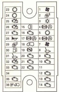
Main fuse box
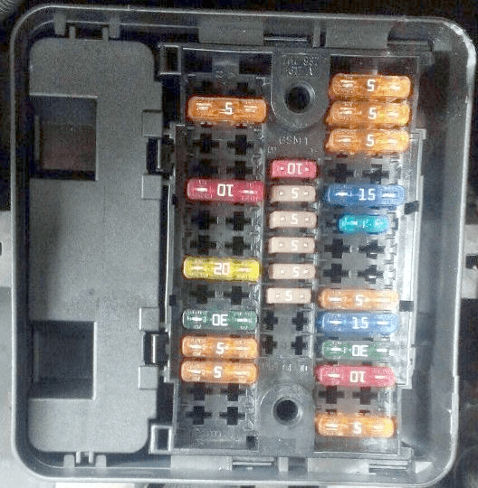
photo.
| Diagram | |
|---|---|
|
|
| № | Amps / Description |
| 1 | (5A) Cooling fan (s) motor (s) |
| 2 | (5A) Coolant pump relay |
| 3 | (15A) Air conditioning (5A) Crankcase ventilation resistor |
| 4 | (30A) Anti-lock braking system (ABS) or Voltage stabilizer, Stereo, Radio |
| 5 | (15A) Automatic transmission |
| 6 | (30A) Anti-lock braking system (ABS) |
| 7 | (5A) Cooling fan motor control unit 1 (7.5A) Washer pump |
| 8 | (15A) Engine management |
| 9 | (5A) Engine management, main ignition circuit relay |
| 10 | (5A) Engine management (15A) Charge or exhaust valve |
| 11 | (5A) Power steering control unit (30A) Headlamp switch and headlight relay |
| 12 | (5A) Engine management (10A) Fuel pressure regulator |
| 13 | (10A) Engine management (10A) Xenon in the left headlight |
| 14 | (5A) Engine management or fuel pump relay |
| 15 | (10A) Reversing light switch |
| 16 | (5A) Engine management or brake light switch, air mass meter |
| 17 | (5A) Anti-lock braking system (ABS) |
| 18 | (5A) Power steering |
| 19 | (5A) Brake light switch (brake pedal position sensor), clutch pedal position sensor |
| 20 | (5A) Engine management |
| 21 | (5A) Exhaust gas recirculation valve |
| 22 | (10A) Engine management (injectors) |
| 23 | (25A) Automatic transmission (10A) Xenon headlight right |
| 24 | (5A) Automatic transmission |
| 25 | (25A) Engine management, Ignition |
| 26 | (25A) Engine management (5A) LH headlight |
| 27 | (5A) Coolant pump relay |
| 28 | (15A) High tone signal |
| 29 | (10A) Vehicle speed sensor (5A) Right headlight |
| 30 | (15 / 20A) A / C / heater auxiliary pump relay, fuel pump, fuel pump relay |
| 31 | (15A) Engine management (lambda probe) |
| 32 | (30A) Engine management (ignition) (5A) Fuel pump relay |
| 33 | (5A) Coolant pump relay engine management, glow plug relay |
| 34 | (10A) Cooling fan motor control unit (5A) Bot network control unit |
| 35 | (10A) Engine management (15A) Fuel level regulator |
| 36 | (25A / 30A) Starter relay (5A) Data bus interface |
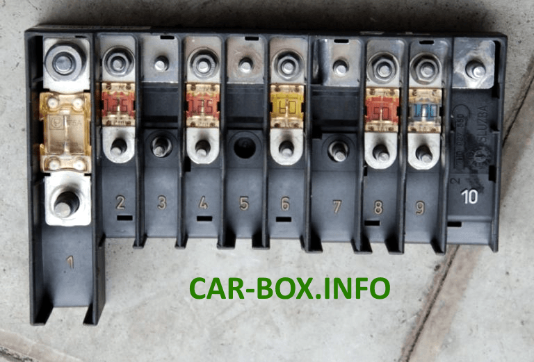
High power fuse box
Located next to the assembly and connected to the battery.
| Photo diagram | |
|---|---|
|
|
| № | Amps / Description |
| 1 | (175 / 225A) Generator |
| 2 | (125A) Battery power distribution, auxiliary ignition relay, driver's door control unit, passenger door control unit, rear window defroster, terminal X relay, separate fuses |
| 3 | (50A / 100A) Charging system (with additional battery), rear left door electrical control unit (some models), rear right door electrical control unit (some models), relay - divider in the charging system (with additional battery) |
| 4 | (125A) Battery power distribution (70A) Positive connection in engine compartment wiring harness |
| 5 | (50A) Battery power distribution (some models), separate fuses |
| 6 | (60A) Glow plug relay (50A) Exhaust air pump motor |
| 7 | (70/80 / 100A) Cooling fan (s) motor |
| 8 | (40/50 / 100A) Cooling fan (s) motor, separate fuses |
| 9 | (100A) Battery power distribution, ignition switch |
| 10 | - |
Relay box
Also located next to the fuse box.
| Diagram | |
|---|---|
| № | Description |
| Type 1 | |
|
|
| 1 | Air conditioning electronic control unit (manual temperature control) |
| 2 | Fuel pump relay 2 |
| 3 | Outlet air pump relay |
| 4 | Relay for main ignition circuits |
| 5 | Fuel pump relay 1 |
| 6 | A / C compressor electromagnetic clutch relay (automatic temperature control) |
| 7 | Automatic transmission control relay |
| 8 | Power steering control unit |
| 9 | Coolant pump relay |
| Type 2 | |
|
|
| 1 | Air conditioning electronic control unit (manual temperature control) |
| 2 | Fuel pump relay 2 |
| 3 | Outlet air pump relay |
| 4 | Relay for main ignition circuits |
| 5 | Fuel pump relay 1 |
| 6 | A / C compressor electromagnetic clutch relay (automatic temperature control) |
| 7 | - |
| 8 | Coolant pump relay |
| 9 | Starter relay - if equipped |
In the passenger compartment
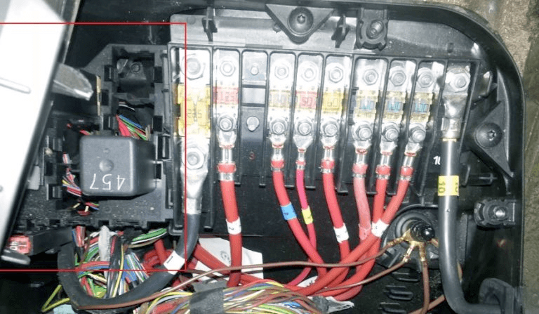
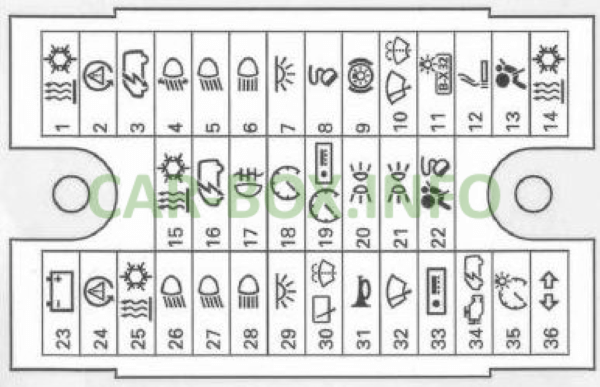
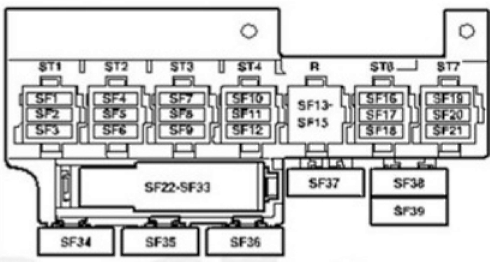
Main fuse box
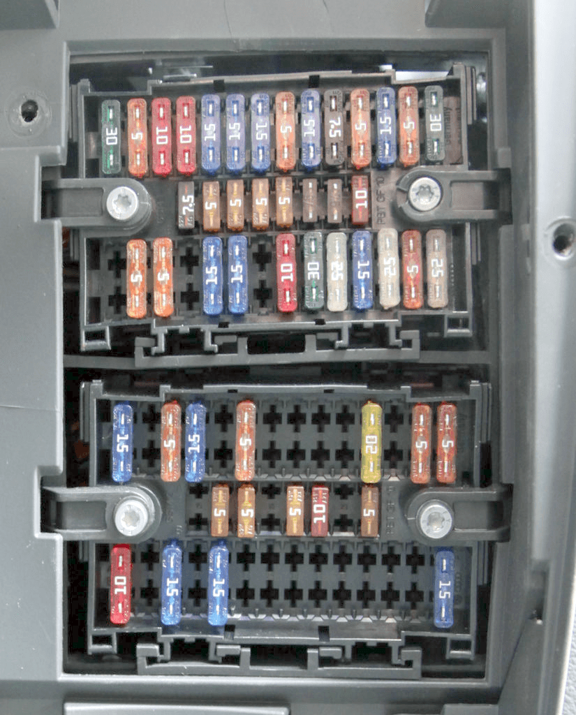
Photo.
| Upper section diagram | |
|---|---|
|
|
| № | Amps / Legend |
| 1 | (25A / 30A) Heater, air conditioner, terminal 15 power relay |
| 2 | (5A) Steering wheel position sensor |
| 3 | (10A) Multifunction control module 1 (onboard supply) |
| 4 | (10A) Headlight range control (5A) Lane change assist |
| 5 | (15A) Left headlight bulb |
| 6 | (15A) Left headlight bulb |
| 7 | (15A) Multifunction control module 1 (interior lamp or vehicle electrical system) |
| 8 | (5A) Diagnostic connector (DLC) (15 / 20A) sliding roof and door control unit, tailgate |
| 9 | (15A) Brake light switch (brake pedal position sensor) (30A) Onboard supply control unit |
| 10 | (10A) Windshield wiper, rear window wiper |
| 11 | (5A) License plate lamp |
| 12 | (15A) Cigarette lighter (5 / 30A) Light switch |
| 13 | (5 / 10A) SRS electronic control unit |
| 14 | (30A) Auxiliary heater heater, air conditioning (25A) Headlight switch |
| 15 | (7.5) Air conditioning (fan switch and relay) |
| 16 | (5A) Multifunction control module |
| 17 | (5A) Rear fog lamps, instrument cluster |
| 18 | (5A) Instrument cluster control module |
| 19 | (5A) Audio system, instrument cluster control unit, multifunction control unit 1, navigation system, special vehicle equipment |
| 20 | (5A) Front left-hand, left-hand brake light, tail-light-left, or differential lock |
| 21 | (5A) Front light RH, brake light RH, tail light RH or starter relay, ECM |
| 22 | (7.5 / 10A) Passenger airbag deactivation indicator, diagnostic connector (DLC), instrument cluster control unit |
| 23 | (5 / 30A) Starter relay (some models with manual transmission) |
| 24 | (5A) Steering wheel position sensor |
| 25 | (7.5A) Air conditioner (fans) |
| 26 | (30A) Headlamp switch |
| 27 | (15A) Right headlight bulb |
| 28 | (15A) Headlamp high beam indicator, right headlight |
| 29 | (10A) Tailgate signal relay |
| 30 | (10A) Heated windscreen washer nozzles, rear window wiper motor |
| 31 | (30A) Multifunction control module 1 (horn) |
| 32 | (25 / 30A) Multifunction control module 1 (windscreen wiper motor) |
| 33 | (15A) Audio system, navigation system, traffic information control module |
| 34 | (25A) Automatic transmission control system, fuse / relay box, engine compartment 1 |
| 35 | (5A) Instrument cluster illumination |
| 36 | (25A) Multifunction control module 1 (direction indicators) |
| According to the diagram, fuse number 12 is responsible for the VW Caravelle / Multivan cigarette lighter. | |
| Lower section diagram | |
|---|---|

|
|
| № | Amps / legend |
| 1 | (25A) Trailer electrical connector (15A) 10-pin connector |
| 2 | (5A) Anti-theft system |
| 3 | (5A) Heater air conditioner auxiliary fan, left and right (10 / 15A) Optional equipment |
| 4 | (10A) Transfer case control module (differential) |
| 5 | (10A) Accessory connector or 6-pin connector |
| 6 | (5A) Engine oil condition sensor (level, temperature) |
| 7 | (10A) Roof fan (30A) Anti-theft alarm |
| 8 | (5A) Parking system |
| 9 | (5A) Steering column control module (cruise control) |
| 10 | (30A) Audio system (10A) Headlight range control, instrument lighting level |
| 11 | (20A) Anti-theft alarm horn, multifunction control module 2, power sliding door, tailgate opener control module (15A) Walkie-talkie, anti-theft system |
| 12 | (5A) LH headlight (10A) Brake light off relay (30A) Onboard power supply control |
| 13 | (5A) Cruise control main switch, multifunction steering wheel control |
| 14 | (5A) Telephone, RH headlight (30A) Onboard power supply management |
| 15 | (5A) Automatic transmission or Telephone and voice control |
| 16 | (5A) Audio system navigation, telephone (7.5A) TV tuner |
| 17 | (7.5A) Multifunction control module (interior lamp, dimmable mirror) |
| 18 | (5A) Air conditioner (some models) |
| 19 | (5A) Auto dimming interior rearview mirror |
| 20 | (10A) Multifunction control module 1 (heated door mirrors) |
| 21 | (5A) Anti-theft system or rain sensor |
| 22 | (5A) Air conditioning or pressure sensor |
| 23 | (5A) Auxiliary heater and accessories |
| 24 | (7.5A) Interior lamps |
| 25 | (15A / 25A) Heated seats |
| 26 | (10A) Tachograph (if equipped) |
| 27 | (15A) Fog lights or power supply relay |
| 28 | (5A) Rearview mirror adjustment switch, door mirror heaters |
| 29 | (25A) Auxiliary heater |
| 30 | (5A) Auxiliary heater |
| 31 | (25A) Hatch (5A) Onboard charger |
| 32 | (20A) Headlamp washers and its relay |
| 33 | (5A) Tachograph (if equipped) |
| 34 | (15A) Auxiliary power supply connector 3 (rear) (5A) Multifunction steering wheel control module |
| 35 | (10A) Multifunction control unit 1 (reversing light (s), with automatic transmission) (20A) Onboard supply control unit |
| 36 | (5A) Camping equipment control unit, special vehicle equipment |
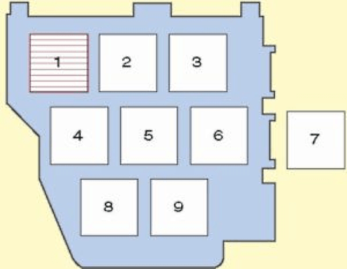
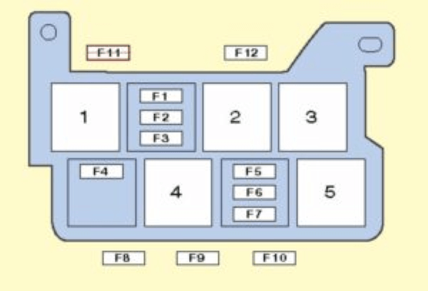
Relay box
Locaed behind the main fuse boxes.
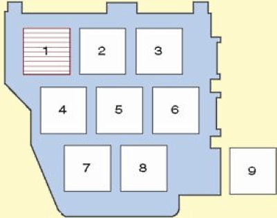
| Diagram | |
|---|---|
| Type 1 | |

|
|
| № | Legend |
| 1 | - |
| 2 | Relay 1 auxiliary heater |
| 3 | A / C blower motor relay, rear |
| 4 | Relay for auxiliary ignition circuits |
| 5 | - 06/03: Rotating beacon relay (special purpose vehicle) |
| 6 | Brake light cut-off relay |
| 7 | Headlight washer pump relay |
| 8 | A / C / heater auxiliary pump relay |
| F1 | - |
| F2 | (30A) Door control module (driver), door control module (passenger) |
| F3 | (40A) Heated rear window |
| Type 2 | |
|
|
| № | Legend |
| 1 | A / C blower motor relay, rear (some models) |
| 2 | Steering column electronics control unit |
| 3 | Steering column electronics control unit |
| 4 | Roof fan relay 1 |
| 5 | Differential lock control unit |
| 6 | 06/03: Tailgate signal relay |
| F1 | (15A) Siren (special purpose vehicle) |
| F2 | (10A) Siren (special purpose vehicle) |
| F3 | (10A) Rotating beacon (special vehicle) |
| F4 | (40A) Rear left door control module (ECM) |
| F5 | (40A) 01/04: Right rear door control module |
| F6 | (5A) 01/04: Voice synthesizer (if available) |
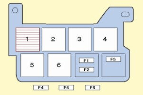
Additional fuse block
Lcated under the driver's seat
| Diagram | |
|---|---|
| Type 1 | |
|
|
| № | Legend |
| 1 | Relay - divider in the charging system (with additional battery) |
| 2 | - |
| 3 | Relay - divider in the charging system (with additional battery) |
| 4 | Special vehicle equipment |
| 5 | Special vehicle equipment |
| F1 | (5A) Camping equipment control box |
| F2 | (10A) Accessory Power Socket 1 (Front), Refrigerator (RV) |
| F3 | (5A) Fresh water pump (camper) |
| F4 | (10A) Interior lamps, local lighting (commercial vehicle) |
| F5 | (30A) Bodywork power connector control module (commercial vehicle) |
| F6 | (40A) Roof lift control module (commercial vehicle) |
| F7 | (5A) Antenna unit |
| F8 | (25A) Additional heater |
| F9 | (30A) Heater air conditioner blower motor (automatic temperature control) |
| F10 | - |
| F11 | - |
| F12 | - |
| F13 | (40A) Rear right door control module |
| F14 | (80A) Additional battery |
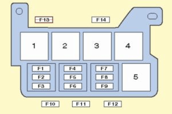
| Type 2 | |
|
|
| № | Description |
| 1 | - |
| 2 | Relay-divider in the charging system (with additional battery) |
| 3 | Special vehicle equipment |
| 4 | Special vehicle equipment |
| 5 | Special vehicle equipment |
| F1 | (15A) Accessory power connector (s) |
| F2 | (15A) Accessory power connector (s) |
| F3 | (15A) Accessory power connector (s) |
| F4 | (15A) Refrigerator (RV), special vehicle equipment |
| F5 | (5A) Antenna unit |
| F6 | (25A) Additional heater |
| F7 | (30A) Air conditioner / heater blower motor (automatic temperature control) |
| F8 | - |
| F9 | - |
| F10 | - |
| F11 | (40A) Rear right door control module |
| F12 | (80A) Additional battery |
| Type 3 | |
|
|
| № | Legend |
| 1 | 5A - 10-pin connector / 6-pin connector |
| 2 | 3A - 10-pin connector |
| 3 | 5 / 15A - 10-pin connector or emergency data logger |
| 4 | 15A - 10-pin connector |
| 5 | 5A - 10-pin connector |
| 6 | 25A - 6-pin connector |
| 7 | 15/30 - 12V socket, voltage converter |
| 8 | 20 / 25A - Heater (heater) control unit |
| 9 | 25 / 30A - Supply fan |
| 10 | 15 / 30A - Climate control |
| 11 | 15A - Cigarette lighter |
| 12 | 5A - 10-pin connector / 6-pin connector |
| 13 | Local relay |
| 14 | Local relay |
| 15 | Local relay |
| 16 | 30A - On-board charger |
| 17 | 30A - Roof hydraulics control unit |
| 18 | 10A - Lighting plafonds |
| 19 | 10A - Cooled compartment |
| 20 | 5A - Water pump |
| 21 | 5A - Camper equipment control panel |
| 21 | 15A - 12V socket |
| 22 | 15A - 12V socket |
| 23 | 10A - Roof fan or 12V socket |
| 24 | 15A - Trailer recognition control unit |
| 25 | 20A - Trailer recognition control unit |
| 26 | 20A - Trailer recognition control unit |
| 27 | 7.5A - Trailer recognition control unit |
| 28 | Spare |
| 29 | 5A - Voice amplifier control unit |
| 30 | Spare |
| 31 | Spare |
| 32 | 15A - Lumbar support for the driver's seat |
| 33 | 40A - Right sliding door control unit |
| 34 | 80A - Control unit for charging the second battery |
| 35 | 40A - Left sliding door control unit |
| 36 | 40A - Supply fan |
| 37 | 6-pin connector |
| 38 | Spare |
