In this article, we will take a detailed look at the fuse diagrams for the Volkswagen Atlas car (first generation / factory index CA1): 2016, 2017, 2018, 2019, 2020, 2021, 2022, 2023 of release.

Fuse number 40 in the passenger compartment is responsible for protecting the electrical circuit of the cigarette lighter.
In the engine compartment

There are two fuse boxes in the engine compartment.
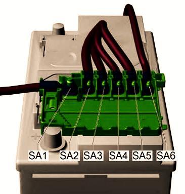
Block #1
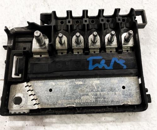
located on the battery. Consists of high power fuse links.
| Diagram | ||
|---|---|---|
|
||
| No. | Description | Amps |
| SA1 | Generator with voltage regulator | 400 |
| SA2 | - | - |
| SA3 | radiator fan | 100 |
| SA4 | Fuse box in the passenger compartment: No. 3, 15, 19, 21, 23, 28, 30, 43, 45, 50 | 80 |
| SA5 | Trailer Circuit Breaker, Front Passenger Seat Adjustment Circuit Breaker 1, Power Relay Terminal 15, Relay Sockets, Interior Fuse box: #4, 12, 14, 22, 38, 40, 42, 46, 51, 53. | 125 |
| SA6 | Power steering control unit | 80 |
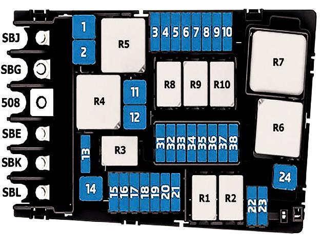
Block #2
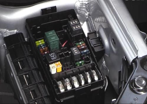
Located behind a protective cover near the battery.
| Diagram | ||
|---|---|---|
|
||
| No. | Description | Amps |
| R1 | Starter relay 1 -J906- | |
| R2 | Starter relay 2 -J907- | |
| R3 | Horn relay -J413- | |
| R4 | High heat output relay -J360- | |
| R5 |
|
|
| R6 | Automatic glow plug control unit -J179- (petrol) | |
| R7 | Low heat output relay -J359- (diesel) | |
| R8 | Power supply relay for engine components -J757- (2.0l petrol engine) | |
| R9 | Heated windshield relay -J47- | |
| R10 | Heated windshield relay 2 -J611- | |
| SB1 | ABS control module | 25/40 |
| SB2 | ABS control unit | 60 |
| SB3 | The engine control unit | 15 |
| SB4 | Turbocharger Recirculation Valve, EVAP Canister Purge Regulator Valve 1, Exhaust Camshaft Adjustment Valve 1, Oil Level Temperature Sensor, Radiator Fan (Radiator Fan Control Module, Radiator Fan), Fuel Tank Leak Detection Control Module, Coolant Shutoff Valve, Camshaft Adjustment Valve 1 , Coolant circulation valve, Intake manifold guide control valve, Piston cooling nozzle control valve, Oil pressure control valve, Coolant control valve | 10 |
| SB5 | Exhaust cam actuators for cylinders 1-4 A and B, Power supply relay for engine components | 10 |
| SB6 | Stoplight switch | 5 / 7.5 |
| SB7 | Cylinder Block Coolant Valve, Auxiliary Heater Pump, Fuel Tank Leak Detection Control Module, Radiator Shutter Motor, Positive Crankcase Ventilation Heating Element, Coolant Recirculation Pump, Transmission Coolant Valve, Coolant Shutoff Valve | 7.5 / 10 / 15 |
| SB8 |
|
15 |
| SB9 | Exhaust Camshaft Adjustment Valve 1, Camshaft Adjustment Valve 1, EVAP Canister Purge Regulator Valve 1, Auxiliary Heater Pump, Ignition Coil 1-6 with Power Output Stage | 10 / 20 |
| SB10 | Fuel pump fuse | 20 |
| SB11 | Not involved | - |
| SB12 | Not involved | - |
| SB13 | transmission control module | 30 |
| SB14 | Heated windshield relay | 40 / 60 |
| SB15 | Horn relay | 15 |
| SB16 | Ignition Coil 1-4 with Power Output Stage, Power Supply Relay for Engine Components | 20 |
| SB17 | Motronic Engine Control Module Power Relay, Engine Control Module, ABS Control Module | 7.5 |
| SB18 | Battery control module | 5 / 7.5 |
| OBD data bus | ||
| SB19 | Wiper Motor Relay | 30 |
| SB20 | Garage door opening control module | 7.5 / 10 |
| SB21 | transmission control module | 15 |
| SB22 | Engine control module | 5 / 7.5 |
| SB23 | Starter | 30 |
| SB24 | Not involved | - |
| SB25 | Not involved | - |
| SB26 | Not involved | - |
| SB27 | Not involved | - |
| SB28 | Not involved | - |
| SB29 | Not involved | - |
| SB30 | Not involved | - |
| SB31 | Not involved | - |
| SB32 | Not involved | - |
| SB33 | Not involved | - |
| SB34 | Not involved | - |
| SB35 | Not involved | - |
| SB36 | Not involved | - |
| SB37 | Additional heater control module | 20 |
| SB38 | Not involved | - |
| SBJ | Power Relay Terminal 15, Front Passenger Seat Adjust Circuit Breaker 1, Trailer Circuit Breaker, Relay Sockets, Interior Fuse Protection: #4, 12, 14, 22, 38, 40, 42, 46, 51, 53. | 125 |
| SBG | Generator with voltage regulator | 40 |
| 508 | Threaded connection - terminal 30 (on the electronics box) / battery | |
| SBE | Power steering control module | 80 |
| SBK | Fuse protection in the passenger compartment: No. 3, 15, 19, 21, 23, 28, 30, 43, 45, 50 | 80 |
| SBL | radiator fan | 80 |
In the passenger compartment
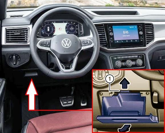
The distribution box is located behind the glove box on the driver's side.
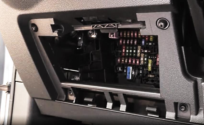
Access example.
| Diagram | ||
|---|---|---|
|
||
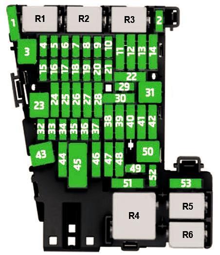
| No. | Description | Amps |
| R1 | Reductant metering system relay -J963- | |
| R2 | empty | |
| R3 | empty | |
| R4 | Terminal 15 supply relay -J329- | |
| R | Heated rear window relay -J9- | |
| R6 | Socket relay -J807- | |
| 1 | Not involved | - |
| 2 | Steering column electronics control module | 10 |
| 3 | Rear blower control module | 30 |
| 4 | On-board network control module | 7,,5 |
| 5 | Remote Start Relay, OBD Data Bus | 7.5 |
| 6 | Ignition Switch Solenoid, Selector Mechanism | 7.5 |
| 7 | Rear Defroster Relay, A/C Rear Display Control Unit, Heater and A/C Control, A/C Clutch Relay, Tire Pressure Monitoring Module | 10 |
| 8 | Driving profile selection control unit, Electromechanical parking brake button, Diagnostic connection, Rain and light sensor, Rotary light switch, Direction indicators and headlight range control module, Dashboard contour lighting lamps, Garage door opener control unit | 7.5 |
| 9 | Ignition/Starter Switch, Steering Column Electronics Control Unit | 7.5 |
| 10 | Front information display control head | 7.5 |
| 11 | On-board network control module | 40 |
| 12 | Information electronics control module 1 | 20 |
| 13 | Not involved | - |
| 14 | Supply air fan control module | 40 |
| 15 | Steering column lock electronic control unit | 10 |
| 16 | USB connection 1 / USB distributor | 7.5 |
| 17 | Emergency call module and communication unit, instrument cluster | 7.5 |
| 18 | Back Cover Handle, Peripheral Camera Control Module, Selector Mechanism | 7.5 |
| 19 | Access/Launch System Interface | 7.5 |
| 20 | Not involved | - |
| 21 | All-wheel drive control unit | 15 |
| 22 | Towing detection control unit | 15 |
| 23 | Electric sunroof control unit | 30 |
| 24 | Onboard power supply control unit | 40 |
| 25 |
|
30 |
| 26 | Onboard power supply control unit | 30 |
| 27 | Onboard power supply control unit | 30 |
| 28 | Towing detection control module | 25 |
| 29 | Pressure sensor in the refrigerant circuit | 5 |
| 30 | Remote start relay | 10 |
| 31 | Back cover control module | |
| 32 |
|
10 |
| 33 |
|
7.5 |
| 34 |
|
7.5 |
| 35 | Diagnostic connector | 7.5 / 10 |
| 36 | Headlight front right | 7.5 / 10 |
| 37 | Headlight front left | 7.5 / 10 |
| 38 | Towing detection control module | 25 |
| 39 | Passenger Side Rear Window Motor, Front Passenger Door Control Module | 30 |
| 40 | Volkswagen Atlas cigarette lighter fuse | 20 |
| 41 | Not involved | - |
| 42 | On-board network control module | 40 |
| 43 | Digital Audio Control Module | 30 / 40 |
| 44 | Towing detection control module | 15 |
| 45 | Fan 1 cushion and backrest front left seat | 15 |
| 46 | Converter with socket, 12V-230V | 7.5 / 30 |
| 47 | Rear window wiper motor | 15 |
| 48 | Not involved | |
| 49 | Starter Relay 1 & 2, Remote Start Relay | 7.5 |
| 50 | Back cover control module | 40 |
| 51 | Air conditioner rear display control unit | 25 |
| 52 | Not involved | - |
| 53 | Rear defroster relay | 30 |
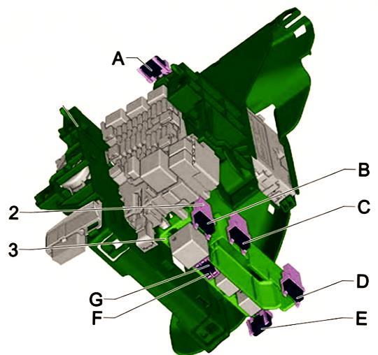
| Separate elements are located near the main block: | ||
|
||
| A | Not involved | - |
| B | Right front seat back and cushion fan 1, Right front seat adjustment control head | 15 |
| C | Not involved | - |
| D | USB charging port 1 | 7.5 |
| E | Pressure sensor in the refrigerant circuit | 5 |
| F | Not involved | - |
| G | Electrical trailer brake position sensor | 25 |
