
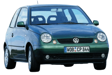
The VW Lupo was primarily produced as a 3-door hatchback from 1998 through 2006. It was positioned as an economical city car. This guide details the fuse and relay assignments for the Volkswagen Lupo (; chassis codes 6X, 6E; PQ24 platform), including block diagrams and location photographs, with the cigarette lighter fuse location specifically highlighted.
Passenger Compartment
Fuse Panel

Located on the driver’s side of the dashboard, below the steering wheel behind a protective cover. To open, pull down using the recessed handle.

Overview.
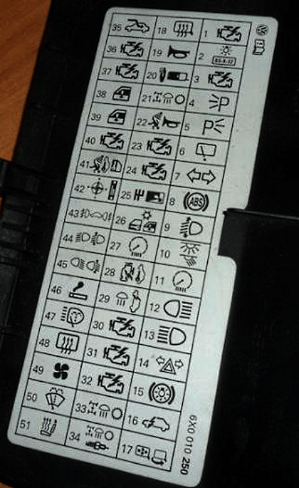
Actual fuse and relay assignments depend on the vehicle’s equipment level and model year. Always cross-reference circuit designations with the legend located on the inside of the fuse panel cover.
| Diagram | |
|---|---|
|
|
| No. | Rating / Circuit Description |
| 1 | 10A Heated oxygen sensor (Lambda sensor) |
| 2 | 5A License plate lights |
| 3 | 10A Fuel injectors |
| 4 | 5A Left side lights / parking lights |
| 5 | 5A Right side lights / parking lights |
| 6 | 15A Rear window wiper |
| 7 | 7.5A Turn signal lights (hazard flasher) |
| 8 | 5A Anti-lock braking system (ABS) with Electronic Stability Control (ESC) |
| 9 | 5A Headlight range control unit |
| 10 | 5A Interior lighting |
| 11 | 5A OBD diagnostic port power supply |
| 12 | 10A Right high-beam headlight |
| 13 | 10A Left high-beam headlight |
| 14 | 10A Hazard warning lights, anti-theft alarm system |
| 15 | 10A Brake lights |
| 16 | 5A Warning chime (lights-on / radio-on reminder) |
| 17 | 5A Power folding exterior mirrors |
| 18 | 5A Heated exterior mirrors |
| 19 | 10A Dual-tone horn, heated windshield washer nozzles |
| 20 | 10A CD changer, cellular phone unit |
| 21 | 5A Automatic transmission system |
| 22 | 15A Anti-theft alarm siren |
| 23 | 5A Cold-start valve, throttle body valve unit, glow plug relay |
| 24 | 5A Clutch pedal switch, direct diesel injection control module |
| 25 | 5A Automatic transmission gear selector lever unit |
| 26 | 5A Fresh air recirculation system |
| 27 | 5A Instrument cluster |
| 28 | 5A Vehicle speed sensor (VSS), engine immobilizer |
| 29 | 7.5A Reversing lights |
| 30 | 5A Exhaust Gas Recirculation (EGR) valve, EVAP canister purge solenoid |
| 31 | 10A Fuel injection system control module |
| 32 | 5A Engine Control Unit (ECU) / Fuel injection unit |
| 33 | 10A Transmission Control Module (TCM) |
| 34 | 10A Ignition system, vehicle speed sensor |
| 35 | 25A Power sunroof motor |
| 36 | 15A Engine Control Unit (ECU) |
| 37 | 15A Engine Control Unit (ECU) |
| 38 | 25A Power window motor (driver side) |
| 39 | 15A Power window motor (front passenger side) |
| 40 | 15A Electric fuel pump |
| 41 | 15A Central locking control module |
| 42 | 15A Radio receiver, navigation system |
| 43 | 15A Front and rear fog lights |
| 44 | 15A Left low-beam headlight |
| 45 | 15A Right low-beam headlight |
| 46 | 15A Cigarette lighter / 12V auxiliary socket |
| 47 | 20A Headlight washer system |
| 48 | 20A Heated rear window defroster |
| 49 | 25A Fresh air blower motor |
| 50 | 15A Windshield wipers |
| 51 | 15A Heated seats |
Fuse No. 46 (15 A) protects the cigarette lighter / 12V power socket.
Relay Panel
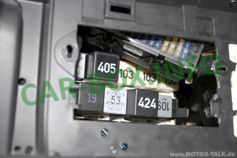
Located directly behind the main passenger compartment fuse panel.
Engine Compartment

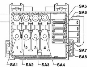
The main distribution box is mounted on top of the battery cover and contains high-current fusible links alongside standard blade fuses.
| Diagram | |
|---|---|
|
|
| No. | Rating - Circuit Description |
| 1 | 110A - Alternator |
| 2 | 80A - Interior relay carrier power feed |
| 3 | 50A - Glow plug system |
| 4 | 30A / 50A - Air conditioning / Engine cooling fan |
| 5 | 30A - Anti-lock braking system (ABS pump) |
| 6 | 30A - Anti-lock braking system (ABS valves) |
| 7 | 20A - Engine cooling fan |
| 8 | 10A - Air conditioning compressor clutch |
