
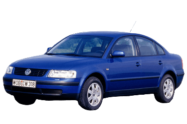
The VW Passat B5 represents the fifth generation of the Passat family, manufactured from 1997 through 2005. Following the 2001 mid-cycle update, it was commonly designated as the Passat B5.5 (B5+) or Passat GP. This article provides a comprehensive overview of the fuses and relays in the Volkswagen Passat B5 (chassis codes 3B, 3BG; PL45 platform), including complete block diagrams, component descriptions, and location photos. Specific locations for the cigarette lighter and fuel pump fuses are highlighted separately.
Fuse and relay assignments may vary depending on vehicle trim level, optional equipment, and model year.
Passenger Compartment
Main Fuse Box
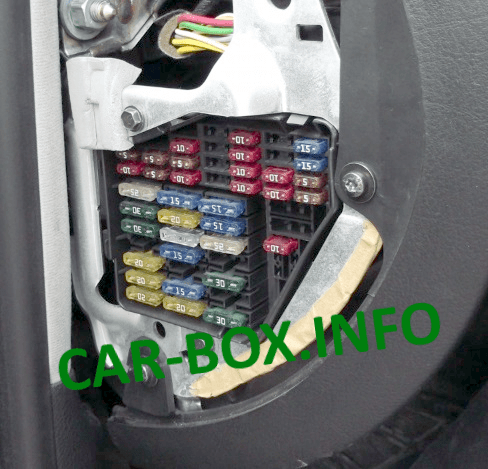
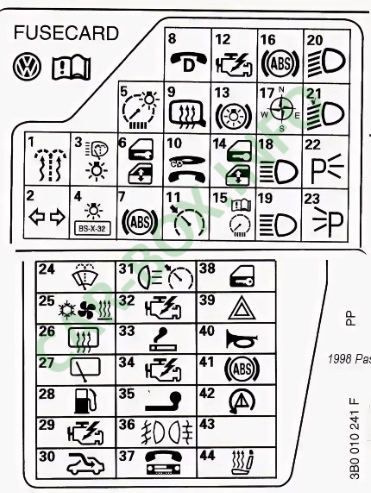
Located on the driver’s side end of the dashboard behind the removable trim panel. An updated fuse assignment diagram or card is typically attached to the inside of the cover.
| Diagram | |
|---|---|
|
|
| No. | Rating / Protected Circuit |
| 1 | 5 A – Heated windshield washer nozzles |
| 2 | 10 A – Turn signal flasher unit |
| 3 | 5 A – Convenience system control unit, cruise control, Climatronic/AC control unit, seat heating control modules, auto-dimming rearview mirror, multifunction steering wheel control module |
| 4 | 5 A – License plate lights |
| 5 | 10 A – Instrument cluster, heated seats, automatic transmission selector display, power mirror switch, airbag control module, outside temperature display, navigation system |
| 6 | 5 A – Central locking system, interior/reading lights |
| 7 | 10 A – ABS control module OR reverse lights, speedometer, vehicle speed sensor (VSS) |
| 8 | 5 A – Cellular telephone |
| 9 | 10 A – Heated door mirrors, door lock cylinder heating |
| 10 | 5 A – Headlight range control, CD changer |
| 11 | 5 A – Cruise control (automatic transmission), instrument cluster |
| 12 | 10 A – Data Link Connector (DLC) / On-Board Diagnostics (OBD) |
| 13 | 10 A – Brake lights (stop lights) |
| 14 | 10 A – Interior lighting, reading lights, anti-theft alarm system, vanity mirror illumination |
| 15 | 10 A – Instrument cluster, automatic transmission, air conditioning, navigation system |
| 16 | 5 A – ABS system |
| 17 | 10 A – Heated door lock cylinders |
| 18 | 10 A – Right high beam headlight |
| 19 | 10 A – Left high beam headlight |
| 20 | 15 A – Right low beam headlight, headlight leveling motor |
| 21 | 15 A – Left low beam headlight, headlight leveling motor |
| 22 | 5 A – Right parking lights / side marker lights |
| 23 | 5 A – Left parking lights / side marker lights |
| 24 | 25 A – Windshield wipers, windshield washer pump, intermittent wiper relay |
| 25 | 30 A – Fresh air blower fan, air conditioning system |
| 26 | 30 A – Heated rear window, heated door mirrors, air recirculation flap |
| 27 | 15 A – Rear window wiper |
| 28 | 15 A – Electric fuel pump |
| 29 | 15 A – Engine management system (ECM) |
| 30 | 20 A – Power sunroof |
| 31 | 15 A / 20 A – Reverse lights, cruise control, automatic transmission, OBD diagnostic connector |
| 32 | 20 A – Engine management system (ECM) |
| 33 | 15 A – Cigarette lighter / 12 V power outlet |
| 34 | 15 A – Engine management system (ignition / fuel injection) |
| 35 | 30 A – Trailer towing socket |
| 36 | 15 A – Front fog lights, rear fog light |
| 37 | 15 A – Cellular telephone, radio / audio head unit |
| 38 | 15 A – Power mirror adjustment, remote fuel filler door release, power windows, central locking |
| 39 | 15 A – Hazard warning flashers |
| 40 | 25 A – Dual-tone horn |
| 41 | 25 A – ABS hydraulic pump OR auxiliary power outlet |
| 42 | 25 A – Radio / 40 A – Auxiliary radiator cooling fan |
| 43 | 5 A – Terminal 86s (S-contact) / 10 A – Engine management |
| 44 | 15 A / 30 A – Heated seats |
Note: Fuse #33 (15 A) protects the cigarette lighter / 12 V socket circuit, while Fuse #28 (15 A) supplies the electric fuel pump. Note that additional fuses and relays also support the fuel delivery system.
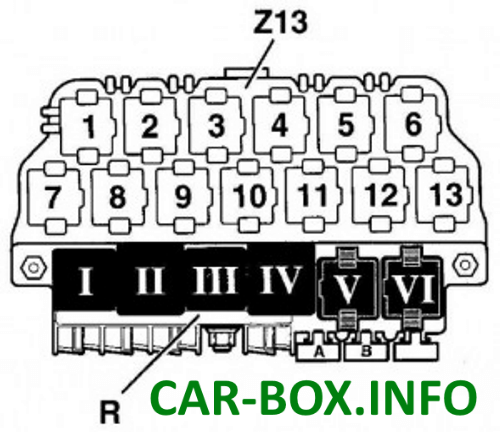
Main Relay Panel
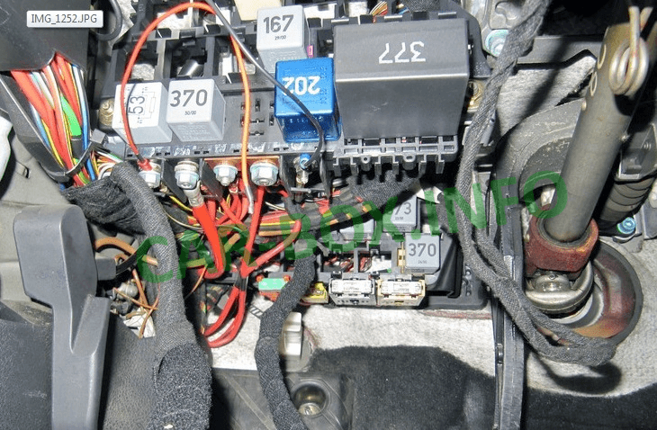
Located under the dashboard on the driver’s side, near the steering column.
| Diagram | |
|---|---|
|
|
| No. | Relay Panel R |
| I | Dual-tone horn relay |
| II | X-contact load reduction relay |
| III | Intermittent wiper control unit |
| IV | Fuel pump relay |
| Glow plug relay (diesel) | |
| V | Unassigned |
| VI | |
| A | Fuse |
| B | |
| No. | Relay Panel Z (13-Position) |
| 1 | Radiator fan relay (air conditioning) |
| 2 | A/C clutch cutoff relay |
| 3 | A/C electromagnetic clutch relay |
| 4 | Air conditioning relay |
| 5 | Fuel pump relay (diesel engines) |
| 6 | Exterior lighting relay |
| Taxi equipment relay | |
| 7 | Headlight washer system relay |
| 8 | Glow plug relay |
| 9 | Unassigned |
| 10 | Fog light relay |
| 11 | Cellular telephone mute / communication relay |
| 12 | Starter motor relay |
| 13 | Starter lockout relay (anti-theft alarm / park-neutral safety switch) |
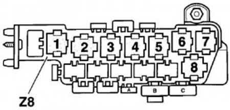
Auxiliary Relay Carrier

Installed on vehicles equipped with expanded electrical options, this 8-position relay carrier is situated directly behind the main relay panel.
| Diagram | |
|---|---|
|
|
| No. | Description |
| 1 | Unassigned |
| 2 | ABS / EDL / ESP control relay |
| 3 | ABS / EDL / ESP power relay |
| 4 | Radiator fan relay (80 W) |
| Radiator fan relay (300 W, Speed 1) | |
| 5 | Radiator fan relay (high speed) |
| 6 | Radiator fan relay (300 W, Speed 2) |
| A | Radiator fan fuse (5 A) |
| B | Radiator fan fuse (30 A) |
| C | ABS hydraulic pump fuse (50 A) |
Engine Compartment
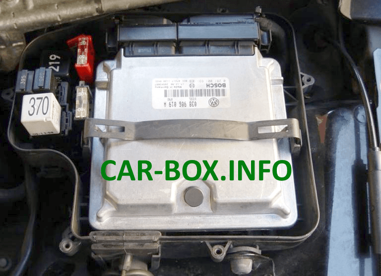
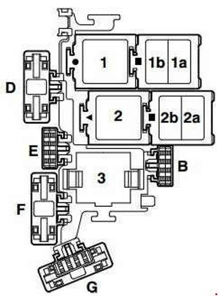
Located inside the protective electronics box (E-box) on the driver’s side, adjacent to the engine control module (ECM).
| Diagram | |
|---|---|
|
|
| No. | Rating / Description |
| B | 10 A – Fuel injector fuse (S116) |
| B | 5 A – Auxiliary coolant pump fuse |
| D | 50 A – Secondary Air Injection (AIR) pump fuse (S130) |
| E | 40 A – Ignition coil circuit fuse (S115) |
| F | 5 A – Engine Control Module (ECM) fuse (S102) |
| G | 10 A – Engine electronics fuse (S282) |
| 1 | Motronic Engine Control Module (ECM) power supply relay (167) [Engine code BDP] |
| 2 | Secondary Air Injection (AIR) pump relay (373 / 100) |
| 3 | Motronic ECM power supply relay (429 / 219) / Auxiliary coolant pump relay (53 / 411) |
