The Audi A1 (body index - 8X) is a subcompact car presented by the German company to the general public in 2010 at the Geneva Motor Show. In this article, we will take a detailed look at the fuse diagrams for the the Audi A1 (8X) of the 1st generation 2010, 2011, 2012, 2013, 2014, 2015, 2016, 2017, 2018 with engines 1.2 TFSI, 1.4 TSI, 1.6 TDI, 2.0 TDI, 2.0TFSI .
Here you will find the locations and photos of distribution boxes. The fuses responsible for the “Cigarette lighter” and “Fuel Pump” are highlighted in bold.
In the engine compartment
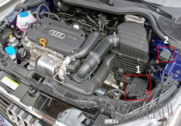
The main unit is the battery (also, depending on the model, it can be in the trunk). Add. block number 2 is located near the battery.
| Diagram | ||
|---|---|---|
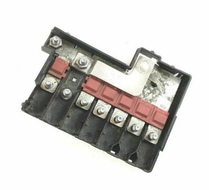
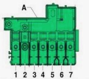
| Block #1 on the battery | ||
|
||
|
||
| No. | Purpose | A |
| FL1 | Generator | 175 |
| FL2 | Heating relay low output | 40 |
| Additional air heater | ||
| FL3 | Source of power | 110 |
| or not used | ||
| FL4 | Power steering control unit | 80 |
| FL5 | Radiator fan control unit | 50/40 |
| Thermostat | ||
| FL6 | Glow plug control unit | 50 |
| FL7 | High performance heating relay | 60 |
| Battery Monitor Control Unit | ||
| Additional air heater | ||
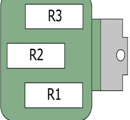
| Add. block #2 | ||
|
||
| R1 | additional coolant pump | |
| R2 | Wiper Relay #1 | |
| R3 | Wiper Relay #2 | |
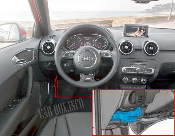
In the passenger compartment
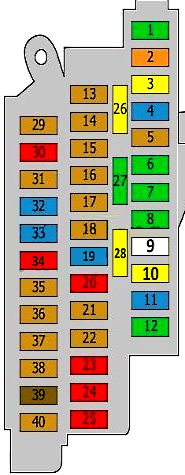
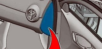
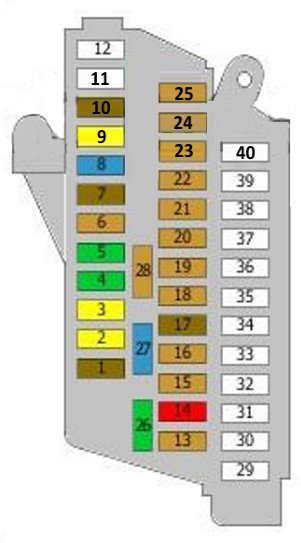
Fuse box #1
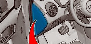
Located on the driver's side in the front dashboard.
Access example.
| Diagram | ||
|---|---|---|
|
||
| No. | Purpose | A |
| 1 | Digital audio control unit | 30 |
| Voltage regulator | ||
| radio tape recorder | ||
| 2 | Heater control unit | 40 |
| Contact X unload relay | ||
| Supply fan control unit | ||
| Supply air fan | ||
| 3 | Cigarette lighter fuse Audi A1 | 20 |
| 12V socket | ||
| 4 | Trailer control unit | 15 |
| 5 | Diagnostic unit | 5 |
| 6 | Door function control units | 30 |
| 7 | 30 | |
| 8 | Rear window heater | 30 |
| 9 | ABS/ESP system | 25 |
| 10 | Multifunction control box | 20 |
| 11 | Sound signals | 15 |
| 12 | Multifunction control box | 30 |
| 13 | Anti-theft system | 5 |
| 14 | Motronic power supply relay | 5/7.5 |
| The engine control unit | ||
| Terminal 30 relay supply voltage | ||
| 15 | Multifunction control box | 5 |
| 16 | ABS control unit | 5 |
| Voltage regulator(s) | ||
| 17 | Cooling fan motor(s) | 5 |
| 18 | Rain and light sensor | 5 |
| mobile phone amplifier | ||
| Phone holder | ||
| Front ceiling module | ||
| 19 | Fuel pump fuse | 15/20 |
| 20 | Coolant pump motor | 10 |
| 21 | Steering column electrical control unit | 5 |
| 22 | Light switch | 5 |
| 23 | Climatronic control unit | 10 |
| Air conditioner control unit | ||
| Front passenger door control unit (up to April 2012) | ||
| Rear right door control unit (until April 2012) | ||
| Plug connector, 16-pin, diagnostic socket | ||
| 24 | Door function control units | 10 |
| 25 | Multifunction control box | 10 |
| 26 | Cooling fan motor(s) | 20 |
| 27 | Multifunction control box | 30 |
| 28 | windshield wiper | 20 |
| 29 | Glow plug control unit | 5/20 |
| Vacuum brake pump | ||
| 30 | Stoplight switch (before October 2011) | 10 |
| Clutch pedal sensor (before October 2011) | ||
| Auxiliary coolant pump relay | ||
| Lambda probe heating element (up to October 2011) | ||
| Power supply for fuse #9 and #10 on fuse box F, (November 2011 to October 2014) | ||
| ABS control unit, from November 2011 | ||
| 31 | Air mass meter, up to October 2014 | 5/7.5/15 |
| Fuel pump relay, before October 2014 | ||
| Relay for low and high heating power, until October 2014 | ||
| Power supply relay for engine components, up to October 2014 | ||
| Fuel pressure control valve, up to October 2014 | ||
| Coolant circulation relay, before October 2014 | ||
| 32 | Engine control unit | 15/30 |
| Clutch pedal position sensor, before October 2011 | ||
| brake light sensor, before October 2011 | ||
| 33 | Engine management | 15/20/30 |
| 34 | Radiator fan control unit, up to October 2014 | 10/15 |
| Heating resistance relay, before October 2014 | ||
| Boost pressure control solenoid valve, up to October 2014 | ||
| Solenoid valve 1 absorber, before October 2014 | ||
| Valve 1 for adjusting the valve timing, up to October 2014 | ||
| Turbocharger bypass valve, up to October 2014 | ||
| Intake manifold valve, before October 2014 | ||
| Exhaust valve 1, up to October 2014 | ||
| EGR cooler changeover valve, up to October 2014 | ||
| Oil pressure control valve, up to October 2014 | ||
| Cylinder 2 and 3 camshaft adjuster for intake and exhaust, up to October 2014 | ||
| EGR cooler pump | ||
| 35 | CD changer | 5 |
| 36 | Radio | 5 |
| TV tuner | ||
| telephone | ||
| Chip card reader | ||
| 37 | Instrument cluster control unit | 5 |
| 38 | Auto-dimming interior rear view mirror | 5 |
| 39 | radio tape recorder | 7.5/15 |
| Information electronics control unit | ||
| 40 | Navigation display unit | 5 |
Fuse box #2
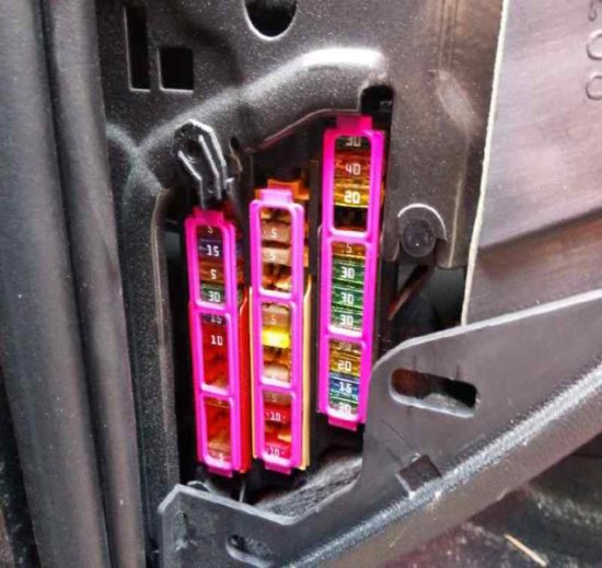
Located on the passenger side at the end of the front dashboard.
| Diagram | ||
|---|---|---|
|
||
| No. | Purpose | A |
| 1 | Steering column lock | 7.5 |
| 2 | Trailer control unit | 20 |
| 3 | 20 | |
| 4 | Transmission | 30 |
| 5 | Headlight washers | 30 |
| 6 | Central locking, GPS | 5 |
| 7 | Remote control system for central locking and engine start | 7.5 |
| 8 | Transmission | 15 |
| 9 | Sunroof | 20 |
| 10 | Transmission | 10 |
| 11 | Reserve | - |
| 12 | Reserve | - |
| 13 | Reversing light switch | 5 |
| Selector sensor control unit | ||
| Mechatronics for dual clutch gearboxes | ||
| 14 | high pressure sensor | 10 |
| Engine oil level and temperature sensor | ||
| Air conditioner control unit | ||
| Socket relay | ||
| Auto-dimming interior rear view mirror | ||
| Connector, 16-pin, diagnostic connector | ||
| 15 | Data bus diagnostic interface | 5 |
| 16 | Heater control unit | 5 |
| Structure noise control unit | ||
| 17 | Light switch | 7.5 |
| Starter relay 1/2 | ||
| Voltage regulator | ||
| Interior rearview mirror relay with automatic dimming function | ||
| Front left and right headlight | ||
| 18 | Light switch | 5 |
| 19 | ABS control unit, up to October 2014 | 5 |
| Voltage stabilizer 2, before October 2014 | ||
| Electronic damping control unit, from January 2014 | ||
| 20 | Driver's seat heating control | 5 |
| Front passenger seat heating control | ||
| Emergency light button | ||
| Heated rear window switch | ||
| ASR and ESP button | ||
| Parking aid activation button | ||
| Tire pressure indicator key | ||
| Start-Stop button | ||
| Trailer detection control unit | ||
| Heating resistor for left and right injectors | ||
| 21 | Power steering control unit | 5 |
| 22 | Air mass meter | 5 |
| Fuel pump control unit | ||
| Crankcase ventilation heating resistor | ||
| 23 | Airbag control unit | 5 |
| Front Passenger Airbag Warning Light Off | ||
| 24 | Parking aid control unit | 5 |
| 25 | Headlight range control unit | 5 |
| 26 | Seat heating control unit | 30 |
| 27 | Rear wiper motor | 15 |
| 28 | Engine control unit | 5 |
| Air mass meter | ||
| 29 -- 40 |
Reserve | - |
Relay box
Located under the dashboard on the driver's side.

General view.
| Diagram | ||
|---|---|---|
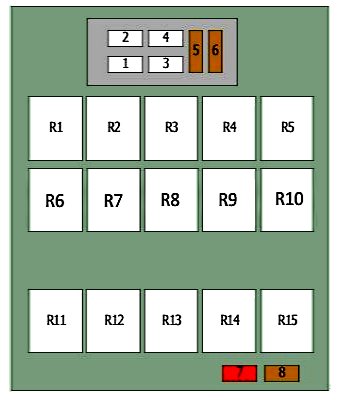
|
||
| No. | Purpose | A |
| 1 | Voltage regulator(s) | 40 |
| 2 | Fuse box No. 2 in the cabin, fuses 1 - 12 | 50 |
| 3 | Terminal 15 supply voltage relay | 40 |
| 4 | ABS control unit | 40 |
| 5 | Voltage regulator(s) | 5 |
| 6 | Power control unit | 5 |
| Voltage regulator(s) | ||
| The engine control unit | ||
| 7 | Stoplight switch; Clutch position sensor | 10 |
| 8 | Oxygen sensors before and after the catalytic converter (depending on equipment) | 5 |
| R1 | Headlight washer relay | |
| signal relay | ||
| R2 | Terminal 15 supply voltage relay | |
| R3 | X contact reset relay | |
| R4 | Audi A1 fuel pump relay | |
| heater relay | ||
| R5 | High performance heating relay | |
| R6 | Starter relay | |
| R7 | Heated rear window relay | |
| R8 | Motronic power supply relay | |
| Power outlet | ||
| Terminal 30 supply voltage | ||
| R9 | Heating relay low output | |
| R10 | Relay Power Socket | |
| Motronic power supply relay | ||
| Terminal 30, supply voltage, relay | ||
| R11 | Automatic anti-glare rearview mirror (if equipped) | |
| R12 | Not | |
| R13 | Voltage regulator(s) | |
| R14 | Not | |
| R15 | Automatic anti-glare rearview mirror (if equipped) | |
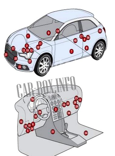
General arrangement
Layout of the electronic components.
|
|
| No. | Component |
| 1 | ABS electronic control module |
| 2 | Electronic air conditioning control module |
| 3 | Battery-Diesel |
| 4 | Battery - gasoline - in luggage compartment |
| 5 | Diagnostic connector |
| 6 | Diagnostic unit |
| 7 | Driver door electrical control module |
| 8 | Left rear door electrical control module |
| 9 | Passenger door electrical control module |
| 10 | Right rear door electrical control module |
| 11 | Electronic Engine Control Module(ECM) |
| 12 | Underhood fuse boxes |
| 13 | |
| 14 | Fuse boxes and relays in the cabin |
| 15 | |
| 16 | |
| 17 | Fuse box and relay in the trunk on the battery (petrol) |
| 18 | glow plug control module |
| 19 | Headlight range control module |
| 20 | Heater blower motor resistor - in heater module |
| 21 | Horn |
| 22 | |
| 23 | Control module for central locking and engine start remote control system |
| 24 | Multifunctional control module |
| 25 | Ambient temperature sensor |
| 26 | Parking system control module |
| 27 | Power steering control module |
| 28 | Seat heating control module |
| 29 | Steering column electrical control module - on the steering column |
| 30 | Steering column lock control module - on the steering column |
| 31 | SRS electronic control module |
| 32 | Trailer Electrical Control Module - LH Trunk |
| 33 | Electronic Transmission Control Module (TCM) - on transmission |
| 34 | Voltage regulator module 1 - under the mat |
| 35 | Voltage Regulator Module 2-in Dashboard Fuse/Relay Module 3 |
| 36 | Battery control module - petrol - in luggage compartment |
| 37 | Cooling fan motor control module |
| 38 | A/C Heater Fan Motor Control Module |
| 39 | Instrument Cluster Control Module |
| 40 | Fuel pump control module - in tank |

Great, at last I have found a site that simply explains the fuse and relay locations and there purpose. Brilliant, well done
Where can I locate the reverse light/parking aid fuse. Can’t seem to see any on the diagrams shown above. Thanks
AUDI A1 sport 999cc