The second generation Audi A6 debuted in the spring of 1997. The car was based on the new C5 platform, the body had the factory designation 4B. The model was produced in sedan and station wagon (Avant) bodies, and the Allroad quattro was subsequently developed on its basis. In this article, we will take a detailed look at the fuse diagrams for the the Audi A6 / Allroad Quattro 2nd generation) index C5) 1999, 2000, 2001, 2002, 2003, 2004, 2005 of release.

Here you will find the locations and photos of distribution boxes. Separately, we note the fuse responsible for the fuel pump and cigarette lighter.
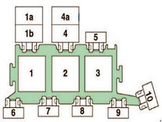
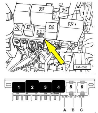
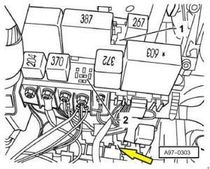
In the engine compartment
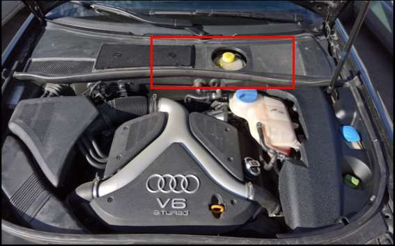
The distribution box is located near the drainage box.
| Diagram | |
|---|---|
|
|
| No. | Description |
| Relay | |
| 1 | secondary air pump - J299 (RS6) |
| 1a | radiator fan (Allroad) - J26 |
| 1b | Coolant bleeding after shutdown engine (Allroad) - J151 |
| add. coolant pump - J496 | |
| 2 | secondary air pump - J299 |
| 3 | Motronic unit power supply - J271 (petrol engines) |
| diesel direct injection system - J322 (diesel engines) | |
| Relay, ABS - J64 (Automatic Transmission - 01J) | |
| 4 | fuel cooling pump - J445 |
| bleeding coolant after shutdown engine - J151 (RS6) | |
| 4a | Not used |
| Circuit breakers | |
| 5 | engine control unit - S102 |
| engine electronics (Allroad) - S282 | |
| 6 | Not used (left-hand drive vehicles) |
| glow plugs - S125 (engines: V6 TDI, V8 TDI) | |
| glow plugs - S39 (four-cylinder engines) | |
| radiator fan - S94 (Allroad) | |
| 7 | glow plugs - S39 (engines: V6 TDI, V8 TDI) |
| secondary air pump - S130 (petrol engines) | |
| auxiliary heater - S62 (right-hand drive vehicles) | |
| Not used (right-hand drive vehicles) | |
| 8 | auxiliary heater - S62 (left-hand drive vehicles) |
| Not used (left-hand drive vehicles) | |
| 9 | glow plugs - S125 (engines: V6 TDI, V8 TDI) |
| glow plugs - S39 (four-cylinder engines) | |
| radiator fan - S94 (Allroad) | |
| coolant pump - S78 (RS6) | |
| Not used (right-hand drive vehicles) | |
| 10 | fuel cooling pump - S262 |
| -1- (15) - S199 (automatic transmission 01J) | |
| radiator fan control unit - S142 (Allroad) | |
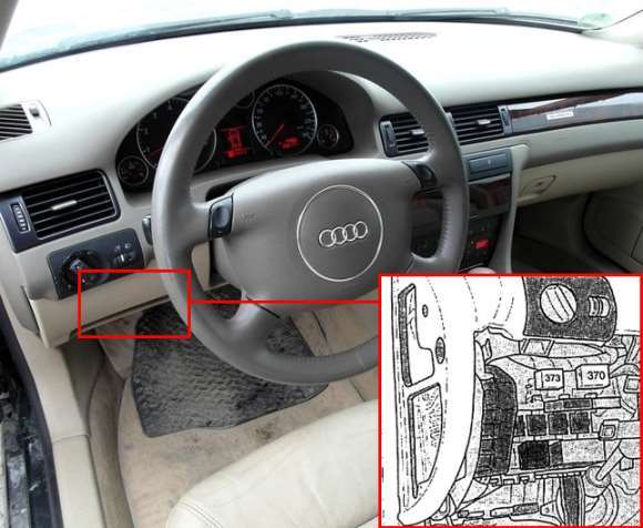
In the passenger compartment
Main fuse box
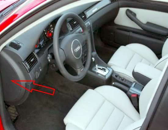
It is located on the left side of the instrument panel (driver's side) under a plastic cover.
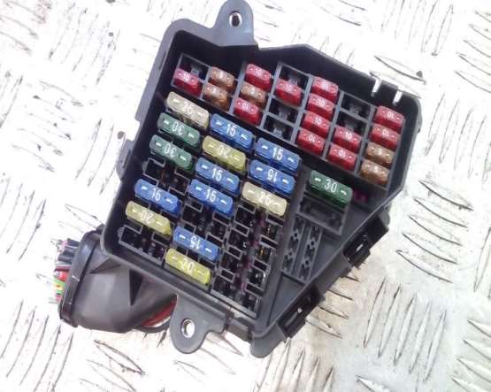
The photo shows an example.
| Assigment of fuses in the main cabin unit | ||
|---|---|---|

|
||
| No. | Description | A |
| 1 | Heater jets, mirrors | 5 |
| 2 | direction indicators | 10 |
| 3 | Lighting. Headlight cleaner relay | 5 |
| 4 | License plate lighting | 5 |
| 5 | Instrument panel, seat heating, diagnostic plug for cruise control, light bulb monitoring unit, catalytic converter, switch illumination, gear indication, airbag warning light, outside temperature gauge, air conditioning, parking heater, rear window blind, sunroof, relief sensors parking, heater, navigation system | 10 |
| 6 | central locking | 5 |
| 7 | ABS system, brake light switch. Clutch pedal switch | 10 |
| 8 | Telephone | 5 |
| 9 | Mirror heater | 10 |
| 10 | Automatic headlight beam throw adjustment | 5 |
| 11 | Cruise control (vehicles with automatic transmission), control unit-gearbox Multitronic | 10 |
| 12 | Self-diagnosis system | 10 |
| 13 | Stop lights | 10 |
| 14 | Interior lighting, reading lights, burglar alarm, vanity mirror lighting, seat memory | 10 |
| 15 | Instrument panel, air conditioning, seat and mirror memory, parking heater timer, navigation system | 10 |
| 16 | Vehicle stability stabilization system | 5 |
| 17 | Navigation system, ride height adjuster | 10 |
| 18 | Right high beam headlight | 10 |
| 19 | Left high beam headlight | 10 |
| 20 | Right dipped beam headlight, headlight range control | 15 |
| 21 | Left dipped beam headlight, headlight range control | 15 |
| 22 | Right marker/parking light | 5 |
| 23 | Left marker/parking light | 5 |
| 24 | Wiper, washer pump, interval relay | 25 |
| 25 | Heater/A/C Fan, Parking Heater | 30 |
| 26 | Rear window defroster, interior air recirculation mode | 30 |
| 27 | Steering wheel heater, rear window wiper | 15 |
| 28 | Petrol pump, additional pump for vehicles with a diesel engine | 20 |
| 29 | The engine control unit. | 30 |
| 30 | Sunroof | 20 |
| 31 | Reversing lights, cruise control, automatic transmission, diagnostic socket | 15 |
| 32 | The engine control unit | 20 |
| 33 | Cigarette lighter fuse Audi A6 / Allroad Quattro | 15 |
| 34 | The engine control unit | 15 |
| 35 | Drawbar socket | 30 |
| 36 | Fog lights, rear fog light | 15 |
| 37 | Telephone, radio | 20 |
| 38 | Trunk lamp, central locking | 20 |
| 39 | Light alarm | 15 |
| 40 | Sound signal | 25 |
| 41 | ABS, stability stabilization system | 25 |
| 42 | Vehicle stability stabilization system | 25 |
| 43 | Radio terminal S | 5 |
| 44 | Seat heater, parking heater | 30 |
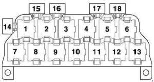
Additional relay boxes
Located behind the dashboard.
| Assigment of elements in the central distribution block | |
|---|---|

|
|
|
|
| Circuit breakers | |
| A | steering column adjustment - S275 |
| B | rear curtain - S100 |
| C | burglar alarm control unit II - S181 (taxi) |
| C - S204 (police cars) | |
| emergency exit rear cover - S195 (special vehicles) | |
| multifunction steering wheel control unit - S326 | |
| Relay | |
| 1 | horn - J4 |
| 2 | unloading X contact - J59 |
| 3 | lower range hydraulic pump - J555 (Allroad) |
| 4 | fuel pump - J17 (petrol engines) |
| glow plugs - J52 (diesel engines) | |
| 5 | wiper and washer - J31 |
| 6 | |
| 13-slot fuse and relay box | |
|---|---|
|
|
| No. | Purpose |
| Relay | |
| 1 | horn - J4 |
| 2 | generator connection - J442 |
| Burglar alarm control unit - J85 (taxi) | |
| siren - J408 (police cars) | |
| burglar alarm, light switch - J549 (special vehicles) | |
| 3 | Solar isolation relay -J309 |
| Burglar alarm control unit - J85 (taxi) | |
| siren - J408 (police cars) | |
| Burglar alarm relay, high beam alarm - J461 (special vehicles) | |
| 4 | starter lock -J207 |
| starter interlock and reverse light - J226 | |
| 5 | magnetic clutch - J44 |
| auxiliary heater - J8 | |
| 6 | fog light - J5 |
| Fuel pump - J17 (TDI engines) | |
| 7 | Multifunction steering wheel control unit - J453 |
| 8 | |
| 9 | Lamp Monitor - J123 |
| 10 | |
| 11 | Folding mirror control unit - J351 |
| 12 | |
| 13 | Servotronic control unit - J236 |
| Circuit breakers | |
| 14 | taximeter - S182 |
| E - S201 (police cars) | |
| Hydraulic Pump Relay Fuse - S279 (Allroad) | |
| 15 | Not used |
| 16 | burglar alarm - S57 (taxi) |
| B - S202 (police cars) | |
| 17 | taximeter and burglar alarm - S183 (taxi) |
| C - S203 (police cars) | |
| radio - S253 (special vehicles) | |
| fog lights - S28 (daytime running lights - Canada) | |
| 18 | Installed in any free space |
| Alternator connection relay - J442 (special vehicles) | |
| Burglar alarm control unit II - J430 (taxi) | |
| Light Relay - J182 (Police Vehicles) | |
| Solar battery isolation relay -J309 (taxi) | |
| 8-slot block | |
|---|---|
This relay box is located behind the central switchgear. |
|

|
|
| No. | Description |
| 1 | Solenoid valve relay - ABS with ESP - J106 |
| 2 | Radiator Fan Relay (2nd Speed) - J101 |
| 3 | Radiator Fan Relay - J26 |
| Coolant bleed relay after engine shutdown -J151 | |
| 4 | Radiator Fan Enable Relay - J138 |
| 5 | Not used |
| 6 | Air Suspension Compressor Relay - J403 (Allroad) |
| 7 | Hydraulic Pump Relay - ABS with ESP - J105 |
| 8 | Coolant Shutoff Valve Relay - J541 |
| 14 | Driver Seat Adjust Thermal Fuse - S44 (Allroad) |
| 15 | Fuse 12V connector - S184 |
| 16 | Thermal fuse for front power windows - S37 |
| 17 | Thermal fuse for rear power windows - S43 |
| 18 | ABS unit fuse - S123 |
| 19 | Radiator fan fuse - S42 |
| 20 | Radiator fan control unit fuse - S142 |
| 21 | Driver seat adjustment thermal fuse - S44 |
| Radiator Fan Fuse - S42 (Allroad) | |
| 22 | Air suspension fuse - S110 (Allroad) |
| 24 | Passenger seat adjustment thermal fuse - S80 |
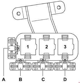
| Diagram of a 3-slot block | |
|---|---|
|
|
| No. | Purpose |
| A | Not used |
| B | |
| C | Additional heater fuse 2 - S143 |
| Hydraulic pump fuse (brake booster) - S279 | |
| Fuel pump fuse - S81 (RS6 LHD) | |
| D | Additional heater fuse - S109 |
| Fuel pump fuse - S81 (RHD RS6) | |
| 1 | Low heating power relay - J359 |
| Brake booster relay - J569 | |
| 2 | Auxiliary heater relay - J8 |
| Solar isolation relay - J354 | |
| 3 | High heating power relay -J360 |
