The fourth generation of the Audi A6 (C7) business sedan was launched in early 2011. The presentation of the car took place at the North American International Auto Show in Detroit. The car is characterized by pronounced sporty proportions, which compares favorably with many rivals in the business class. In this article, we will take a detailed look at the fuse box diagrams for the Audi A6 (C7) of the 4th generation of 2010, 2011, 2012, 2013, 2014, 2015, 2016, 2017, 2018 of release.
Here you will find the locations and photos of distribution boxes. The fuses responsible for the “Cigarette lighter” and “Fuel Pump” are highlighted in bold.
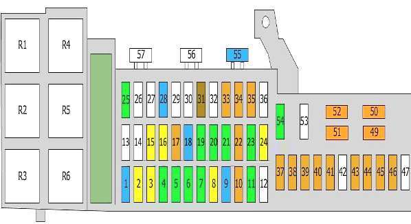
In the luggage compartment
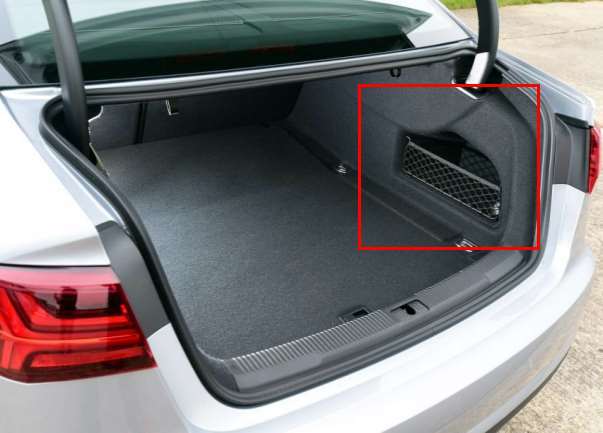
The distribution box is located on the right side of the trunk, under the net. To access it, you need to remove the casing.
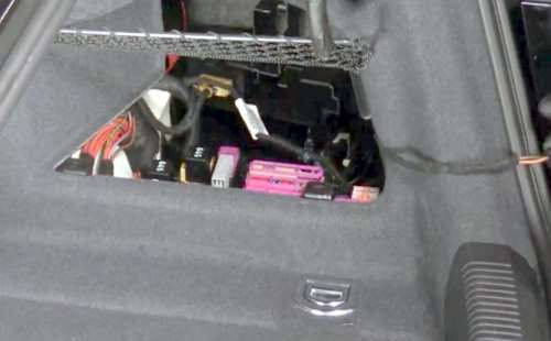
Access example.
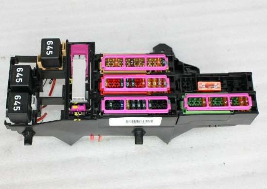
General view.
| Diagram | ||
|---|---|---|
|
||
| No. | Description | A |
| 1 | Trailer detection control module | 15 |
| 2 | Trailer detection control module | 20/10 |
| Cup holder with heating and cooling element | ||
| 3 | Trailer detection control module | 20 |
| 4 | Parking brake module | 30 |
| 5 | 30 | |
| 6 | Front Passenger Door Control Module | 30 |
| 7 | Comfort control module | 30 |
| 8 | 20 | |
| 9 | seat ventilation | 15 |
| 10 | connector | 5 |
| 11 | Air conditioner control module | 30 |
| Seat heating control module | ||
| 12 | empty | - |
| 13 | Seat belt pretensioner | 25 |
| 14 | 25 | |
| 15 | Audi A6 cigarette lighter fuse | 20 |
| Socket 12V | ||
| DC-AC converter with socket, 12 V - 230 V | ||
| 16 | Rear cigarette lighter | 20 |
| Additional sockets 12V | ||
| 17 | Electric parking brake | 5 |
| 18 | Adaptive Suspension Control Module | 15 |
| 19 | Rear Right Door Control Module | 30 |
| 20 | Comfort control module | 30 |
| 21 | Control device | 30 |
| 22 | telephone | 5 |
| 23 | Audio control module | 30 |
| 24 | Adjustable rear spoiler control module | 20 |
| 25 | Audio control module | 30/20 |
| Information display control module | ||
| Radio | ||
| 26 | Fuel Tank Leak Control Module | 5 |
| 27 | empty | - |
| 28 | Engine Mount Control Module | 15 |
| Reductant control module | ||
| 29 | empty | - |
| 30 | empty | - |
| 31 | radio tape recorder | 7.5 |
| 32 | Multimedia control module | 7.5 |
| Information display control module | ||
| Information display | ||
| 33 | Automatic anti-glare rear view mirror | 5 |
| 34 | Rear view camera system | 5 |
| 35 | TV tuner | 5 |
| 36 | empty | - |
| 37 | Terminal 15 supply voltage relay | 5 |
| 38 | Parking brake control module | 5 |
| 39 | Adaptive Suspension Control Module | 5 |
| 40 | Comfort control module | 5/7.5 |
| Clutch position sensor | ||
| Selector lever control module | ||
| 41 | Parking Assist Control Module | 5 |
| 42 | empty | - |
| 43 | Voltage regulators | 5 |
| 44 | Lane Change Assist Control Module | 5 |
| 45 | Diagnostic socket (16) | 5 |
| Power management module | ||
| 46 | 4WD control module | 5 |
| 47 | empty | - |
| 48 | empty | - |
| 49 | Adaptive Suspension Compressor Relay | 40 |
| 50 | Voltage regulator(s) | 40 |
| 51 | Heated rear windshield relay | 40 |
| 52 | Voltage regulator(s) | 40 |
| 53 | 4WD control module | 35 |
| 54 | Reductant Dosing System Relay (If Equipped) | 30 |
| 55 | Main fuse (if installed) | 15 |
| 56 | empty | - |
| 57 | empty | - |
| R1 | Not used | |
| R2 | Heated rear window relay | |
| R3 | Relay Power Socket | |
| R4 | Terminal 15 supply voltage relay | |
| R5 | Adaptive Suspension Compressor Relay | |
| R6 | Not used | |
In the passenger compartment
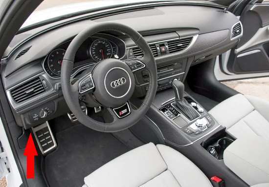
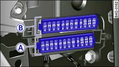
On the driver's side
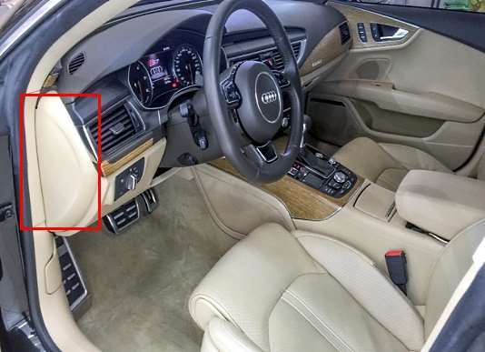
The first block is located at the end of the dashboard behind a plastic cover on the driver's side.
Access example.
| Diagram | ||
|---|---|---|
|
||
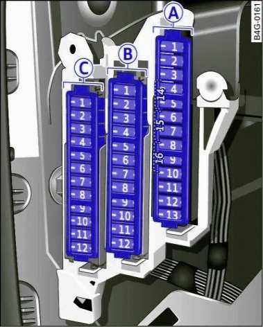
| Panel -A- (black) | ||
| No. | A | Purpose |
| 1 | 5 | Switch panel, seat heating, start assist, control unit, tow bar |
| 2 | 5 | Auto-shielded interior rearview mirror |
| 3 | 10 | Exhaust System (Diesel) |
| 4 | 5 | Chassis control sensor |
| 5 | 5 | ESP control unit |
| 6 | 5 |
|
| 7 | 10 | Audi adaptive cruise control |
| 8 | 5 | Airbag control unit, front passenger seat sensors |
| 9 | 5 | Gateway |
| 10 | 5 | "HomeLink" (Garage Door Opener), Night Vision Assist Control Unit |
| 11 | 10 | Image processing ("Audi active lane assist", "Audi adaptive cruise control") |
| 12 | 5 | Dynamic control |
| 13 | 15 | terminal 15 in luggage compartment |
| 14 | 30 | terminal 15 on the connection panel (passenger's side) |
| 15 | 15 | terminal 15 in the engine compartment |
| 16 | 40 | Starter |
| Panel -B- (brown) | ||
| No. | A | Purpose |
| 1 | 5 | Gateway |
| 2 | 10 | air conditioner; |
| 3 | 10 | ESP control unit |
| 4 | 30 | Front door (driver's side) |
| 5 | 7.5 | Power seat adjustment (driver's seat) |
| 6 | 35 | Dynamic control |
| 7 | 20 | sliding sunroof |
| 8 | 15 | Rear door (driver's side) |
| 9 | 5 | Lumbar support (front passenger seat) |
| 10 | 30 | Heater |
| 11 | 20 | Sliding sunroof, rear spoiler |
| 12 | 15 | Front door (driver's side) |
| Panel -C- (red) | ||
| No. | A | Purpose |
| 1 | 5 | clutch pedal |
| 2 | 25 | Fuel pump fuse |
| 3 | 5/5 | Brake Light Sensor/Brake Pedal Sensor System |
| 4 | 5/15 | SCR tank (diesel) / engine acoustics |
| 5 | 30 | Rear door (driver's side) |
| 6 | 7.5 | Power seat adjustment (front passenger seat) |
| 7 | 15 | Horn |
| 8 | 30 | Windscreen wipers |
| 9 | 5 | Light/rain sensor |
| 10 | 5 | Lumbar support (driver's seat) |
| 11 | 15 | Front Door (Passenger Side) |
| 12 | 15 | Rear Door (Passenger Side) |
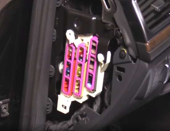
Under the dashboard
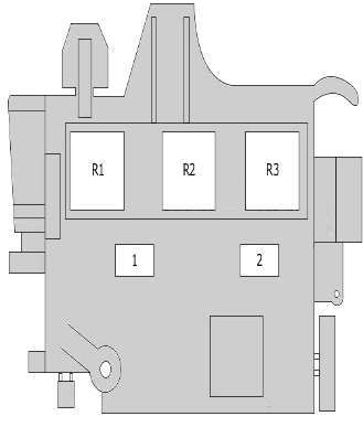
Additional boards with relay modules are located under the dashboard.
| Relay block #1 | ||
|
||
| No. | Description | A |
| 1 | heating elements | 40 |
| 2 | 60 | |
| R1 | Low power heating relay | |
| R2 | High power heating relay | |
| R3 | Additional air heater control unit | |
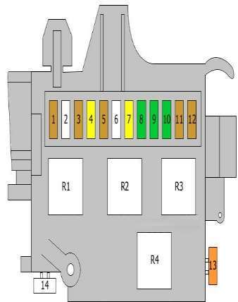
| Block #2 | ||
|
||
| No. | Description | A |
| 1 | Terminal 15 supply voltage relay | 5 |
| 2 | empty | - |
| 3 | Control device | 5 |
| 4 | ABS control unit | 20 |
| 5 | Security alarm | 5 |
| 6 | Power control unit | 35 |
| 7 | Power control unit | 20 |
| 8 | Power control unit | 30 |
| 9 | Power control unit | 30 |
| 10 | Power control unit | 30 |
| 11 | Interior interior lighting | 5 |
| Control unit, roof electronics | ||
| 12 | Auxiliary heater remote control receiver | 5 |
| 13 | ABS control unit | 40 |
| 14 | empty | - |
| R1 | signal relay | |
| Automatic anti-glare rear view mirror | ||
| R2 | Terminal 15 supply voltage relay | |
| R3 | Vacuum pump relay | |
| R4 | - | |
On the passenger's side
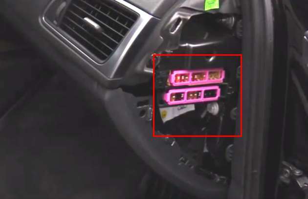
The second fuse box is located behind a plastic cover on the passenger side.
| Diagram | ||
|---|---|---|
|
||
| Panel -A- (black) | ||
| No. | A | Purpose |
| 1 | 5 | Head-up display |
| 2 | 5 | MMI display front |
| 3 | 5 | CD/DVD changer |
| 4 | 7.5 | Front center console MMI |
| 5 | 5 | Chip card reader (depending on the country) |
| 6 | 5 | Dashboard |
| 7 | 5 | Steering switch module |
| 8 | 5/7.5 | Headlight range adjustment/corner light |
| 10 | 7.5 | Headlight on the left (headlight with cornering light) |
| 11 | 5 | Additional heater |
| Panel -B- (brown) | ||
| No. | A | Purpose |
| 1 | 10 | air conditioning; |
| 2 | 40 | air conditioner fan |
| 3 | 10 | Diagnostic interface |
| 4 | 5 | Electric ignition switch |
| 5 | 5 | Electric steering column adjustment |
| 6 | 10 | Steering switch module |
| 7 | 25 | Electric steering column adjustment |
| 8 | 5 | Control unit 1 (on-board network) |
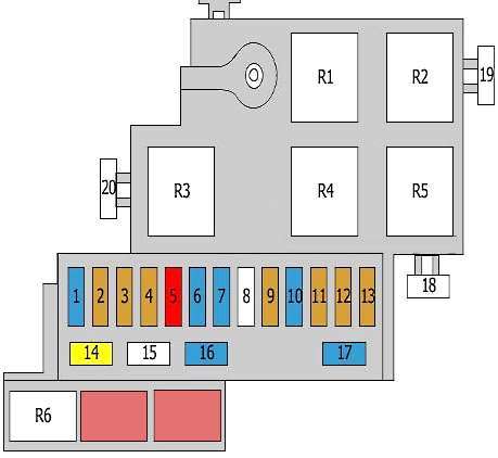
In the engine compartment

The fuse box is located behind the protective lining on the left side of the engine compartment.
| Diagram | ||
|---|---|---|
|
||
| No. | Description | A |
| 1 | Automatic transmission control unit | 15 |
| 2 | Oil level and temperature sensor | 5 |
| 3 | The engine control unit | 5 |
| 4 | The engine control unit | 5 |
| 5 | Fuel metering valve | 10 |
| 6 | The engine control unit | 15 |
| 7 | camshaft valve | 15 |
| Exhaust camshaft solenoid valves | ||
| coolant circulation pump | ||
| 8 | empty | - |
| 9 | Voltage regulators | 5 |
| 10 | Oxygen sensor before catalytic converter | 15 |
| Oxygen sensor behind catalytic converter | ||
| 11 | Fan control unit | 5 |
| Cooling fan control unit 2 | ||
| 12 | Automatic transmission control unit | 5 |
| 13 | Transmission oil cooling valve | 5 |
| 14 | Ignition coils 1 - 6 | 20 |
| 15 | empty | |
| 16 | Secondary air pump relay | 15 |
| additional coolant pump | ||
| Canister purge valve | ||
| intake manifold adjustment valve | ||
| Oil pressure control valve | ||
| Refrigerant circulation solenoid valve | ||
| 17 | Oxygen sensors behind the catalytic converter | 15 |
| 18 | empty | - |
| 19 | secondary air pump | 50 |
| 20 | empty | - |
| R1 | Secondary air pump relay | |
| R2 | Starter relay | |
| R3 | Power supply relay | |
| R4 | Main relay | |
| R5 | Relay, additional water pump | |
| R6 | empty | |
