A6 is a family of business class cars produced under the Audi brand, the internal designation is “type C”. In this article, we will take a detailed look at the fuse diagrams for the the Audi A6 / S6 (index C6) of the 3rd generation 2004, 2005, 2006, 2007, 2008, 2009, 2010, 2011 of release.
Here you will find the locations and photos of distribution boxes. The fuses responsible for the “Cigarette lighter” and “Fuel Pump” are highlighted in bold.
In the trunk
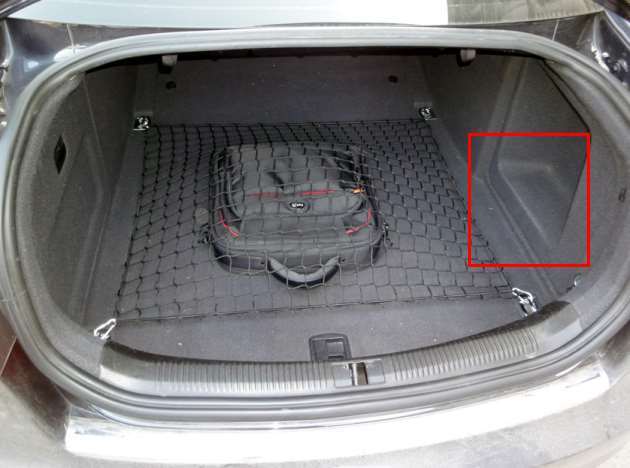
The distribution box is located on the left under the skin, near the jack.
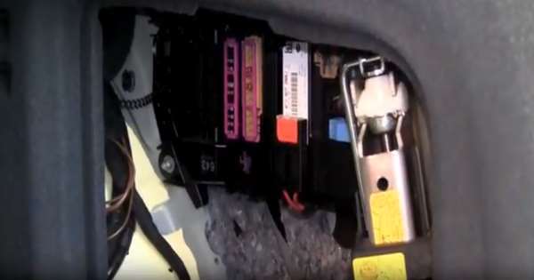
Access example.
| Diagram | ||
|---|---|---|

|
||
| No. | Description | A |
| Black panel | ||
| 1 | Digital/ Signal Processing (DSP)/ BOSE Amplifier | 30 |
| 2 | MMI, antenna amplifier | 5 |
| 3 | Electromechanical parking brake, left motor | 30 |
| 4 | Electromechanical parking brake, right motor | 30 |
| 5 | Socket in the trunk | 20 |
| 6 | Battery - Power Distribution System | 5 |
| 7 | Intelligent Power Distribution Unit (light on the right) | 20 |
| 8 | Rear Intelligent Power Distribution Unit | 5 |
| 9 | Rear Smart Power Distribution Unit (light left) | 30 |
| 10 | Power windows (right side of vehicle) | 35 |
| 11 | Left-hand drive models: Parking assistance. 20A Right-hand drive models: front cigarette lighter | 5 |
| 12 | Rear cigarette lighter | 20 |
| Brown panel | ||
| 1 | Reversing parking camera | 5 |
| 2 | Power tailgate | 30 |
| 3 | 30 | |
| 4 | 20 | |
| 5 | Antenna amplifier | 5 |
| 6 | TV tuner | 5 |
| 7 | Intelligent Power Distribution Unit (Comfort) | 5 |
| 8 | Heater | 20 |
| 9 | digital tuner | 5 |
| 10 | Drawbar control unit | 15 |
| 11 | Traction - coupling device (left lamp) | 15 |
| 12 | Traction - coupling device (right lamp) | 15 |
| 8 - Rear defroster relay, 9 - since 2006: Auxiliary heater fuel pump relay, 10 - Fuel pump relay. | ||
In the passenger compartment
There are three blocks.
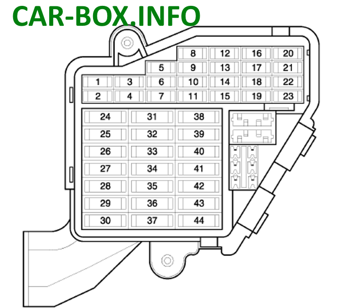
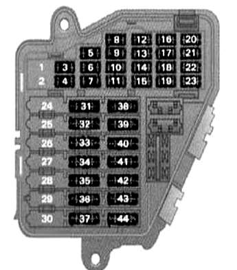
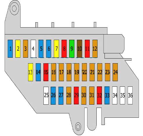
Fuse box #1
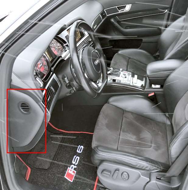
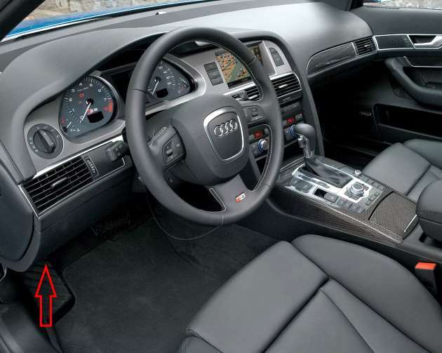
Located at the end of the dashboard on the driver's side.

Access example.
2004 - 2008 model year
Diagram.
|
||
| No. | Purpose | A |
| 1 | Spare | - |
| 2 | Spare | - |
| 3 | engine management | 5 |
| 4 | oil level sensor | 5 |
| 5 | air conditioning | 5 |
| 6 | electronic stability program (ESP), clutch sensor | 5 |
| 7 | diagnostic plug | 5 |
| 8 | homelink control unit | 5 |
| 9 | automatically shielded interior rear view mirror | 5 |
| 10 | distance maintenance (adaptive cruise control) | 5 |
| 11 | heater | 5 |
| 12 | diagnostic plug | 10 |
| 13 | steering column switch module | 10 |
| 14 | brake light switch | 5 |
| 15 | instrument cluster | 10 |
| 16 | telephone, telematics, mobile phone | 10 |
| 17 | electronic stability program (ESP) | 10 |
| 18 | left headlight electronics | 5 |
| 19 | rain sensor | 5 |
| 20 | heated windshield washer jets | 5 |
| 21 | antenna amplifier | 5 |
| 22 | is absent | - |
| 23 | electromechanical parking brake | 5 |
| 24 | is absent | - |
| 25 | is absent | - |
| 26 | is absent | - |
| 27 | is absent | - |
| 28 | is absent | - |
| 29 | is absent | - |
| 30 | is absent | - |
| 31 | reversing light switch, multitronic transmission, engine component | 15 |
| 32 | intelligent driver power module (footwell lighting and headlights, horn, wiper, electric steering column adjustment) | 30 |
| 33 | intelligent driver power module (lighting on the left) | 25 |
| 34 | intelligent driver power module (lighting on the right) | 25 |
| 35 | heater | 20 |
| 36 | headlight cleaner | 30 |
| 37 | electronic stability program (ESP) | 25 |
| 38 | wiper | 30 |
| 39 | left door control unit | 15 |
| 40 | horn / MMI display | 25 |
| 41 | heater fan | 40 |
| 42 | electronic ignition/electric steering column control unit | 30 |
| 43 | is absent | - |
| 44 | advanced key control unit / airbag | 15 |
2008 - 2011 model year
Diagram.
|
||
| No. | A | Purpose |
| 1 | - | Not used |
| 2 | - | |
| 3 | 5 | Engine management |
| 4 | 5 | Audi a6 oil level sensor fuse |
| 5 | 5 | Climate control, tire pressure monitoring system |
| 6 | 5 | Electronic Stability Program (ESP), clutch sensor |
| 7 | 5 | Diagnostic connector |
| 8 | 5 | Home Link control unit |
| 9 | 5 | Auto dimming interior mirror |
| 10 | 5 | Adaptive cruise control |
| 11 | - | Not used |
| 12 | 10 | Diagnostic connector |
| 13 | 10 | Steering column switch module |
| 14 | 5 | 2008: brake light switch |
| 2009-2011: not used | ||
| 15 | 10 | Instrument Cluster, Gateway Control Module |
| 16 | 10 | Phone, cell phone |
| 17 | 10 | Electronic Stability Program (ESP) |
| 18 | 5 | Headlight electronic, left |
| 19 | 5 | Rain sensor |
| 20 | 5 | Heated washer nozzles |
| 21 | 10 | Seat adjustment (driver) |
| 22 | 5 | MMI display |
| 23 | 5 | Electromechanical parking brake |
| 24 | - | Not used |
| 25 | - | Not used |
| 26 | - | Not used |
| 27 | - | Not used |
| 28 | - | Not used |
| 29 | - | Not used |
| 30 | - | Not used |
| 31 | 15 | Reversing light switch, transmission, engine components |
| 32 | 30 | Intelligent driver power module (footlights and headlights, horn, wiper system, electrically adjustable steering wheel) |
| 33 | 25 | Intelligent driver power supply (backlit on the left) |
| 34 | 25 | Intelligent driver power supply (backlit on the right) |
| 35 | Not used | |
| 36 | 30 | Headlight washer system |
| 37 | 25 | Electronic Stability Program (ESP) |
| 38 | 30 | Wiper system |
| 39 | 15 | Left door control module |
| 40 | 25 | Sound horn |
| 41 | 40 | heater fan |
| 42 | 30 | Electronic ignition lock control unit / electrically adjustable steering wheel |
| 43 | 15 | Rear wiper (Avant) |
| 44 | 35 | Power window (left) |
Fuse box #2
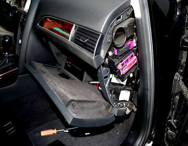
Located at the end of the dashboard on the passenger side.
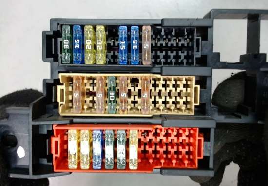
General view.
2004 - 2008 model year
Diagram.
|
||
| No. | Purpose | A |
| 1 | Keyless access control | 5/15 |
| 2 | Audi a6 cigarette lighter fuse | 20 |
| 3 | Tire pressure monitoring control unit | 5 |
| 4 | (Optional equipment power connector | 20 |
| 5 | Supply system | 15 |
| 6 | Door function control units | 15 |
| 7 | Sunroof electric control unit | 20 |
| 8 | Air conditioning electronic control unit | 10 |
| 9 | Electronic control unit for air conditioning, heated front seats | 30 |
| 10 | ^2008: Multifunction display control unit | 5/10 |
| 11 | ^2006: Suspension control unit | 15 |
| 12 | Audio system | 5 |
| 13 | Fuel module (fuel pump fuse) | 20/30 |
| 14 | ^2006: Trailer electrical connector | 10 |
| 15 | ^2006: Not used | - |
| 16 | ^2008: Not used | - |
| 17 | Suspension control unit | 5 |
| 18 | Gear shift control unit | 5 |
| 19 | Parking system control unit | 5 |
| 20 | CAN data bus, gateway control unit | 5 |
| 21 | Headlight range control unit | 5 |
| 22 | SRS electronic control unit | 5 |
| 23 | Seat heater | 5 |
| 24 | ^2006: Not used | - |
| 25 | Special automotive equipment | 25 |
| 26 | 15 | |
| 27 | 15 | |
| 28 | Special vehicle equipment, tachograph | 5/10 |
| 29 | Special automotive equipment | 10/15 |
| 30 | 5/15/10 | |
| 31 | Special vehicle equipment, tachograph, alarm | 5/25/10 |
| 32 | Accessory Power Connector | 15/25/10 |
| 33 | Special automotive equipment | 15 |
| 34 | empty | - |
| 35 | empty | - |
| 36 | empty | - |
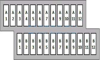
2008 - 2011 model year
Diagram.
|
||
| No. | A | Purpose |
| Panel A (black) | ||
| A1 | 15 | Advanced Key control module |
| A2 | 20 | Front cigarette lighter fuse |
| A3 | 5 | Tire pressure monitoring system |
| A4 | 20 | Front outlet (center console) |
| A5 | 15 | Passenger Intelligent Power Module (Glove Box Lock) |
| A6 | 15 | Right door control module |
| A7 | 20 | Sunroof |
| A8 | 10 | A/C control |
| A9 | 30 | Seat heating front |
| A10 | 10/7.5 | 2008: MMI, Antenna Amplifier (10A); |
| 2009-2011: MMI (7.5A) | ||
| A11 | 10 | Seat adjustment (passenger) |
| A12 | 5 | connection |
| Panel B (brown) | ||
| B1 | 20/30 | Electric fuel pump |
| B2 | 15 | Adaptive air suspension |
| B3 | 10 | lane assistant |
| B4 | 5 | 2008: not used; |
| 2009-2011: Audi Side Assist | ||
| B5 | 5 | Adaptive air suspension |
| B6 | 5 | Automatic transmission shift gear / clutch switch |
| B7 | 5 | Acoustic parking system |
| B8 | 5 | Gateway control module |
| B9 | 5 | Automatic headlight beam throw adjustment (auxiliary high beam), electronic headlight, right side |
| B10 | 5 | Air bag |
| B11 | 5 | Heated rear seats |
| B12 | 5 | telephone |
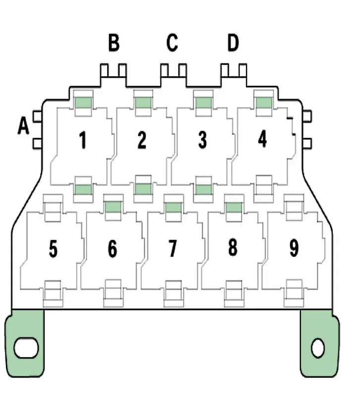
Relay box
Located under the dashboard on the driver's side.

General view.
| Diagram | |
|---|---|
|
|
| No. | Purpose |
| 1 | Supply relay (terminal 15) -J329- |
| 2 | Headlight washer relay -J39- |
| 3 | Spare |
| 4 | Starter relay -J53- |
| 5 | Supply relay (terminal 75x) -J694- (up to 04.2005) |
| 6 | Starter relay 2 -J695- |
| 7 | Signal relay -J4- |
| 7 | Power supply relay (terminal 75x) -J694- (as of 05.2005) |
| 8 | Spare |
| 9 | Spare |
| A | ABS control unit fuse 1 -S123- (40A) |
| B | Spare |
| C | Spare |
| D | Spare |
In the engine compartment
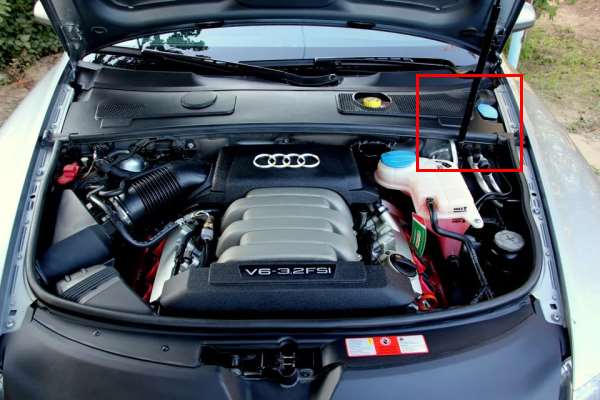
The main distribution box is located near the battery.
| Diagram | ||
|---|---|---|

|
||
| No. | Description | A |
| 1 | Vacuum pump for brake booster | 15 |
| 2 | Engine management system | 15/20/30 |
| 3 | coolant circulation | 10/15 |
| Additional coolant pump | ||
| Exhaust camshaft valve | ||
| Electro-hydraulic left engine mount | ||
| Intercooler coolant pump | ||
| MAP-controlled engine cooling thermostat | ||
| Right electro-hydraulic engine mount solenoid | ||
| Camshaft adjustment | ||
| Swirl solenoid valve | ||
| Intake camshaft valve | ||
| 4 | Electronic engine control unit | 15 |
| 5 | Engine management system | 10/15 |
| 6 | 15 | |
| 7 | 15 | |
| 8 | ^2008: Electronic engine control unit | 5 |
| 9 | Cooling fan motor | 5 |
| 10 | Electronic gearbox control unit | 10 |
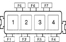
Auxilary fuse box
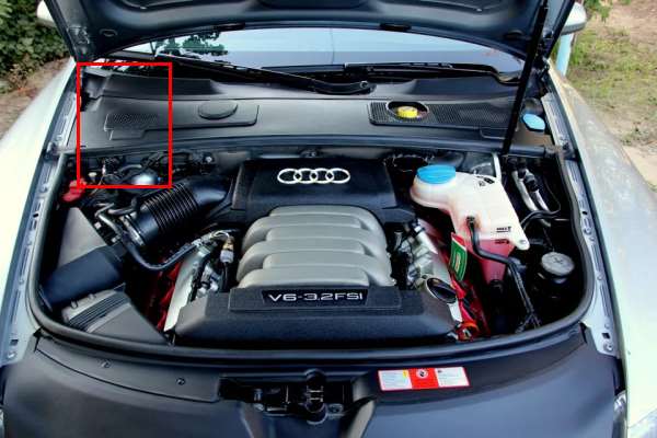
Additional block located on the left.
|
|
| No. | Description |
| F1 | — |
| F2 | (50A) Gasoline: Exhaust air system |
| F3 | (40A) Active suspension system |
| F4 | (15A) Gasoline: Cooling fan motor |
| F5 | — |
| F6 | — |
| F7 | — |
| 1 | — |
| 2 | Active Suspension Compressor Relay |
| 3 | Diesel: Glow Plug Relay |
| 4 | — |
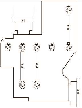
Power fuses
Located on the battery.
| Diagram | |
|---|---|
|
|
| No. | Decryption |
| F1 | empty |
| F2 | Cooling fan motor (40A/60A) |
| F3 | |
| F4 | empty |
| F5 | empty |

I have 5 fuses one is the 30 amp fuel pump fuse the other 4 is 5amp fuses all in General location