A7 (body code - 4G) - a five-door fastback Gran Turismo class manufactured by AUDI AG, on the A6 platform, is positioned in the segment below the A8 model. In this article, we will take a detailed look at the fuse diagrams for the the Audi A7 (4G) of the 1st generation 2010, 2011, 2012, 2013, 2014, 2015, 2016, 2017, 2018 with engines 2.8 FSI, 3.0 TDI, 3.0 TFSI, RS7, 4.0 V8.
Here you will find the locations and photos of distribution boxes. Separately, we note the fuses responsible for the cigarette lighter.
In the engine compartment
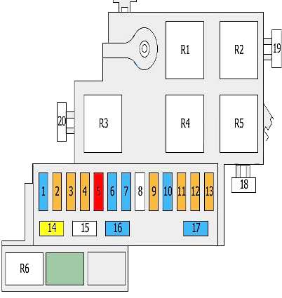
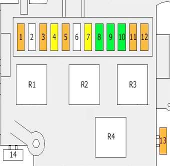
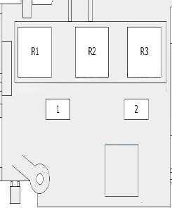
Main fuse box
Located near the battery, behind a protective lining.
| Diagram | ||
|---|---|---|
|
||
| No. | Description | A |
| 1 | Automatic transmission control unit | 15 |
| 2 | Oil level and temperature sensor | 5 |
| 3 | The engine control unit | 5 |
| 4 | 5 | |
| 5 | Fuel metering valve | 10 |
| 6 | The engine control unit | 10 |
| 7 | valve lift valve | 15 |
| camshaft valve | ||
| Exhaust camshaft solenoid valves | ||
| coolant circulation pump | ||
| 8 | empty | - |
| 9 | Voltage regulators | 5 |
| 10 | Oxygen sensor before catalytic converter | 15 |
| Oxygen sensor behind catalytic converter | ||
| 11 | Fan control unit | 5 |
| Cooling fan control unit 2 | ||
| 12 | Automatic transmission control unit | 5 |
| 13 | Transmission oil cooling valve | 5 |
| 14 | Ignition coils 1 - 6 | 20 |
| 15 | empty | - |
| 16 | Secondary air pump relay | 15 |
| Relay, additional water pump | ||
| Canister purge valve | ||
| intake manifold adjustment valve | ||
| Oil pressure control valve | ||
| Refrigerant circulation solenoid valve | ||
| 17 | Oxygen sensors behind the catalytic converter | 10 |
| 18 | empty | - |
| 19 | secondary air pump | 50 |
| 20 | empty | - |
| R1 | Secondary air pump relay | |
| R2 | Starter relay | |
| R3 | Power supply relay | |
| R4 | Main relay | |
| R5 | Relay, additional water pump | |
| R6 | empty | |
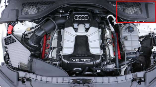
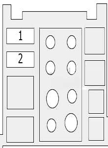
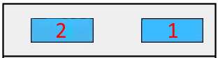
Additional fuse box

Located in the central part of the engine compartment.
| Diagram | ||
|---|---|---|
|
||
| No. | A | Purpose |
| 1 | 40 | radiator (60A /80A also used) |
| 2 | 40 | radiator (60A /80A also used) |
In the passenger compartment
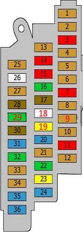
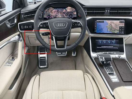
Fuse box #1
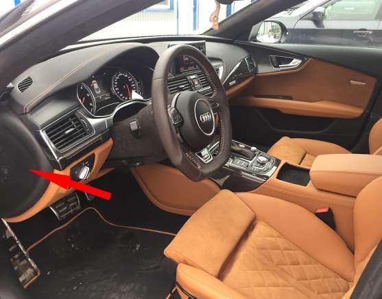
Located on the driver's side.
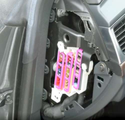
Access example.
| Diagram | ||
|---|---|---|
|
||
| No. | Decryption | A |
| 1 | TCS/ESP button | 5 |
| Air quality improvement control unit | ||
| Power steering control unit | ||
| Seat heating control unit | ||
| Trailer detection control unit | ||
| Electric parking brake | ||
| Passenger side airbag deactivation indicator | ||
| multimedia control unit | ||
| 2 | Automatic anti-glare rear view mirror | 5 |
| 3 | Engine generator sound control unit | 10 |
| 4 | Suspension control sensor | 5 |
| 5 | ABS control unit | 5 |
| 6 | Air quality sensor | 5 |
| Refrigerant pressure and temperature sensor | ||
| 7 | Adaptive cruise control | 10 |
| 8 | Airbag control unit | 5 |
| "Seat occupied" - recognition control unit | ||
| 9 | Data bus diagnostic interface | 5 |
| 10 | Garage door control unit | 5 |
| Night vision control unit | ||
| Sound control unit transmitted through the vehicle body structure | ||
| 11 | Camera control unit | 10 |
| 12 | Active Steering | 5 |
| 13 | Data bus diagnostic interface | 5 |
| 14 | Air conditioning control unit | 10 |
| 15 | ABS control unit | 10 |
| 16 | Driver's door control unit | 30 |
| 17 | Front passenger seat adjustment | 7.5 |
| 18 | Active Steering | 35 |
| 19 | Sunroof | 20 |
| 20 | Rear left door control unit | 15 |
| 21 | Driver seat adjustment | 5 |
| 22 | Additional heater control unit | 30 |
| 23 | Sunroof | 20 |
| Roof blind control unit | ||
| 24 | Driver's door control unit | 15 |
| or not used | ||
| 25 | Clutch position sensor | 5 |
| 26 | Fuel pump control unit | 25 |
| 27 | Stoplight switch | 5 |
| 28 | Exhaust flap control unit | 7.5/5 |
| Or | ||
| Reducer control unit | ||
| 29 | Rear left door control unit | 30 |
| 30 | Front passenger seat adjustment | 7.5 |
| 31 | Signal | 15 |
| 32 | Wiper control unit | 30 |
| 33 | Rain and light sensor | 5 |
| 34 | Driver seat adjustment switch | 5 |
| 35 | Front passenger door control unit | 15 |
| or not used | ||
| 36 | Rear right door control unit | 15 |
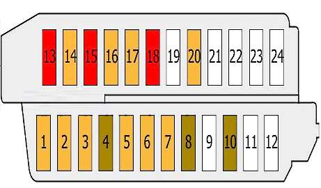
Fuse box #2
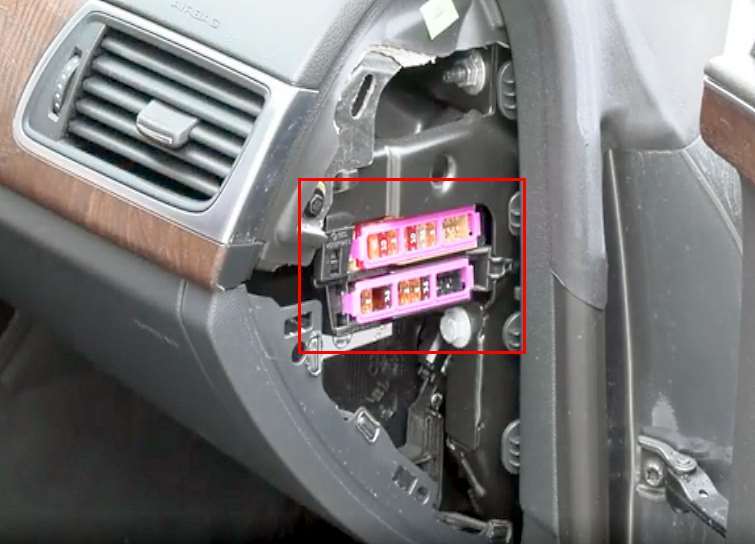
Located at the end of the dashboard on the passenger side.
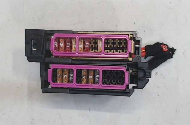
General view.
| Diagram | ||
|---|---|---|
|
||
| No. | Description | A |
| 1 | Head-Up Display Control Unit | 5 |
| 2 | Vehicle information control unit | 5 |
| 3 | CD changer | 5 |
| DVD | ||
| 4 | Information display control unit | 7.5 |
| multimedia control unit | ||
| 5 | Chip card reader | 5 |
| Traffic Message Channel (TMC) Antenna | ||
| 6 | Control Panel | 5 |
| 7 | Control unit, steering column electronics | 7.5 |
| 8 | Headlight range control unit | 7.5 |
| headlight output control unit | ||
| 9 | empty | - |
| 10 | headlight output control unit | 7.5 |
| 11 | empty | - |
| 12 | empty | - |
| 13 | Climatronic | 10 |
| 14 | Supply air fan control unit | 40 |
| 15 | Diagnostic socket (16) | 10 |
| 16 | Electronic anti-theft device | 5 |
| 17 | Steering column lock control unit | 5 |
| 18 | Control unit, steering column electronics | 10 |
| 19 | Steering column adjustment control unit | 25 |
| 20 | Light switch | 5 |
| 21 | empty | - |
| 22 | empty | - |
| 23 | empty | - |
| 24 | empty | - |
Relay blocks
The relay block #3 and #4 is located behind the instrument panel on the driver's side.
| Relay block #3 | ||
|---|---|---|
|
||
| No. | Purpose | A |
| 1 | Terminal 15 supply voltage relay | 5 |
| 2 | empty | - |
| 3 | Control device | 5 |
| 4 | ABS | 20 |
| 5 | Security alarm | 5 |
| 6 | Power control unit | 35 |
| 7 | 20 | |
| 8 | 30 | |
| 9 | 30 | |
| 10 | 30 | |
| 11 | Interior interior lighting | 5 |
| Control unit, roof electronics | ||
| 12 | Auxiliary heater remote control receiver | 5 |
| 13 | ABS control unit | 40 |
| 14 | empty | |
| R1 | signal relay | - |
| Or | ||
| Automatic anti-glare rear view mirror | ||
| R2 | Terminal 15 supply voltage relay | |
| R3 | Vacuum pump relay | |
| R4 | empty | |
| Relay block #4 | ||
|---|---|---|
|
||
| No. | Purpose | A |
| R1 | Low power heating relay | |
| R2 | High power heating relay | |
| R3 | Additional air heater control unit | |
| 1 | Heater | 40 |
| 2 | 60 | |
Auxilar fuse holder
Located at the driver's feet.
|
||
| No. | Purpose | A |
| 1 | Driver seat adjustment | 15 |
| 2 | Passenger seat adjustment | |
In the luggage compartment
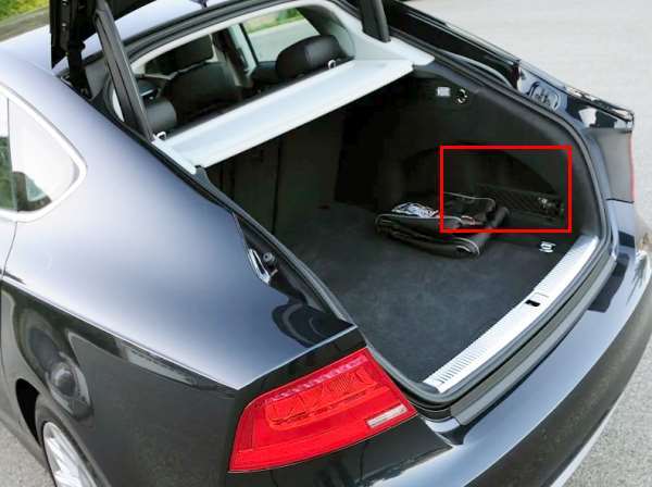
The distribution box is located on the left behind the skin

Access example..
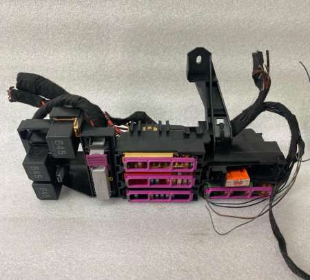
General view.
| Diagram | ||
|---|---|---|

|
||
| No. | Description | A |
| 1 | Trailer detection control unit | 15 |
| 2 | Trailer detection control unit | 20/10 |
| Cup holder with heating and cooling element | ||
| 3 | Trailer detection control unit | 20 |
| 4 | Parking brake control unit | 30 |
| 5 | 30 | |
| 6 | Front passenger door control unit | 30 |
| 7 | Comfort control unit | 30 |
| 8 | 20 | |
| 9 | seat ventilation | 15 |
| 10 | connector | 5 |
| 11 | Air conditioning control unit | 30 |
| Seat heating control unit | ||
| 12 | empty | - |
| 13 | Seat belt pretensioner | 25 |
| 14 | 25 | |
| 15 | Audi A7 cigarette lighter fuse | 20 |
| Socket 12V | ||
| DC-AC converter with socket, 12 V - 230 V | ||
| 16 | Rear cigarette lighter | 20 |
| Additional sockets 12V | ||
| 17 | Electric parking brake | 5 |
| 18 | Adaptive Suspension Control Unit | 15 |
| 19 | Rear right door control unit | 30 |
| 20 | Comfort control unit | 30 |
| 21 | Control device | 30 |
| 22 | telephone | 5 |
| 23 | Audio control unit | 30 |
| 24 | Adjustable rear spoiler control unit | 20 |
| 25 | Audio control unit | 30/20 |
| Information display control unit | ||
| Radio | ||
| 26 | Fuel tank leakage control unit | 5 |
| 27 | empty | |
| 28 | Engine mount control unit | 15 |
| Reducer control unit | ||
| Or | ||
| Reducer control unit | ||
| or not used | ||
| 29 | empty | - |
| 30 | empty | - |
| 31 | radio tape recorder | 7.5 |
| 32 | multimedia control unit | 7.5 |
| Information display control unit | ||
| Information display | ||
| 33 | Automatic anti-glare rear view mirror | 5 |
| 34 | Rear view camera system | 5 |
| 35 | TV tuner | 5 |
| 36 | empty | - |
| 37 | Terminal 15 supply voltage relay | 5 |
| 38 | Parking brake control unit | 5 |
| 39 | Adaptive Suspension Control Unit | 5 |
| 40 | Comfort control unit | 5/7.5 |
| Clutch position sensor | ||
| Selector lever control unit | ||
| 41 | Parking assistance control unit | 5 |
| 42 | empty | - |
| 43 | Voltage regulators | 5 |
| 44 | Lane change assist control unit | 5 |
| 45 | Diagnostic socket (16) | 5 |
| Power control unit | ||
| 46 | 4WD control unit | 5 |
| 47 | empty | - |
| 48 | empty | - |
| 49 | Adaptive Suspension Compressor Relay | 40 |
| 50 | Voltage regulators | 40 |
| 51 | Heated rear windshield relay | 40 |
| 52 | Voltage regulators | 40 |
| 53 | 4WD control unit | 35 |
| 54 | Reductant dosing system relay | 30 |
| or not used | ||
| 55 | Main fuse | 15 |
| or not used | ||
| 56 | empty | - |
| 57 | empty | - |
| R1 | Not used | |
| R2 | Heated rear window relay | |
| R3 | Relay Power Socket | |
| R4 | Terminal 15 supply voltage relay | |
| R5 | Adaptive Suspension Compressor Relay | |
| R6 | Not used | |
