Audi TT is a compact coupe of the German company. Produced since 1998 in Gyor, Hungary. In this article, we will take a detailed look at the fuse diagrams for the the Audi TT (8J) 2nd generation 2006, 2007, 2008, 2009, 2010, 2011, 2012, 2013, 2014 release.
Here you will find the locations and photos of distribution boxes. The fuses responsible for the “Cigarette lighter” and “Fuel Pump” are highlighted in bold.
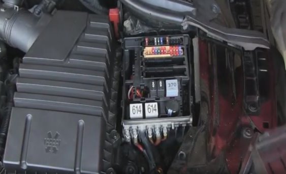
In the engine compartment

The distribution box is located on the left side of the engine compartment. To access, remove the protective cover.
Type 1
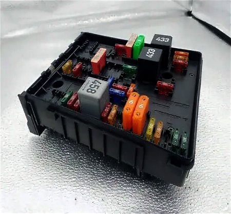
The photo shows an example.
| Assigment of fuses in the engine compartment | ||
|---|---|---|
|
||
| No. | A | Description |
| black panel | ||
| 1 | - | |
| 2 | - | |
| 3 | - | |
| 4 | - | |
| 5 | 5 | burglar alarm (sensor), burglar alarm (horn) |
| 6 | 30 | headlight cleaner audi tt |
| 7 | 15/10 | electric fuel pumps (supply) / fuel flow control valve |
| 8 | 30 | wiper |
| 9 | 25 | seat heating (driver and front passenger) |
| 10 | 10 | lumbar support (driver and front passenger) |
| 11 | - | |
| 12 | 40 | fan |
| Brown panel | ||
| 1 | 15 | petrol pump (6-cyl.) |
| 2 | 10 | lambda probes (6-cyl.) |
| 3 | 5 | air mass meter (6-cyl.) |
| 4 | 10 | lambda probes (6-cyl.) |
| 5 | 5 | relay coil, fuel control valve relay (4-cyl.) |
| 6 | 10 |
secondary air pump valve (6-cyl.), lambda probes (4-cyl.) |
| 7 | 10 | pre-engine wiring set valves |
| 8 | 20/30 | ignition coils (4-cyl.)/ignition coils (6-cyl.) |
| 9 | 25 | engine (control unit) |
| 10 | 10 | water return pump |
| 11 | 5 | power supply (clutch pedal, brake pedal) |
| 12 | 10 | activated carbon filter/boost pressure control - valve (4-cyl.) |
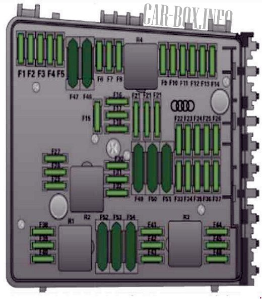
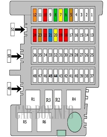
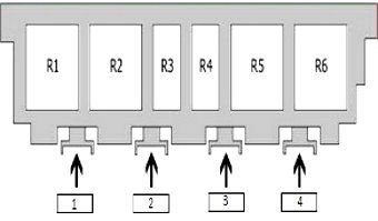
Type 2
Access example.
| Diagram | ||
|---|---|---|
|
||
| No. | Description | A |
| 1 | empty | - |
| 2 | empty | - |
| 3 | empty | - |
| 4 | empty | - |
| 5 | Sound signal; | 5 |
| Security alarm. | ||
| 6 | headlight washer pump | 30 |
| 7 | Fuel pressure control valve | 20 |
| 8 | Wiper control unit | 30 |
| 9 | Heated driver's seat; | 25 |
| Heated front passenger seat. | ||
| 10 | Driver's seat adjustment; | 10 |
| Front passenger seat adjustment. | ||
| 11 | empty | - |
| 12 | Supply fan control unit; | 40 |
| 13 | empty | - |
| 14 | empty | - |
| 15 | empty | - |
| 16 | empty | - |
| 17 | empty | - |
| 18 | oxygen sensor; | 10 |
| 19 | Radiator fan controller; | 10 |
| Fuel system diagnostic pump. | ||
| 20 | Ignition coils | 20 |
| 21 | The engine control unit | 15 |
| 22 | Coolant circulation pump; | 10 |
| 23 | Clutch position sensor | 5 |
| 24 | Power relay; Canister purge solenoid valve; | 10 |
| Valve for adjusting the valve timing; | ||
| Turbo bypass valve; | ||
| Oil pressure control valve. | ||
| 25–51 | empty | |
| R1 | Headlight washer relay (if equipped) | |
| R2 | Fuel pump relay | |
| R3 | Coolant circulation relay | |
| R4 | Secondary air pump relay | |
| R5 | Motronic Power Relay | |
| R6 | Power relay | |
In the passenger compartment
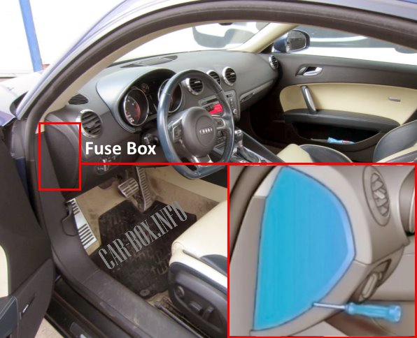
The distribution box is located on the driver's side behind a plastic cover.
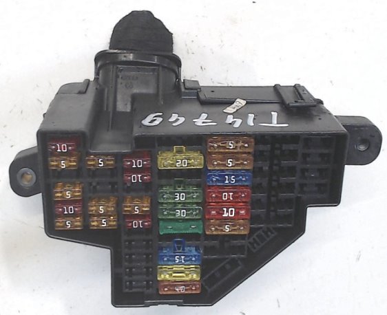
Photo - general view of the board.
| Diagram | ||
|---|---|---|

|
||
| No. | A | Decryption |
| 1 | 10 | engine relay, fuel control unit o engine control unit, airbag-off lamp, light switch (light switches) diagnostic socket |
| 2 | 5 | ABS, ASR, ESP, brake light switch |
| 3 | 5 | AFS headlights (left) |
| 4 | 5 | oil level sensor (WIV), tire pressure indicator, electronic stability control (ESP) switch, AFS headlights (control unit), air conditioning (pressure sensor), reversing light switch |
| 5 | 5/10 | automatic headlight beam throw, AFS headlights (right) / manual headlight beam throw, halogen headlights |
| 6 | 5 | CAN data communication control unit (Gateway), electromechanical power steering, automatic transmission shift gate |
| 7 | 5 | park assist, auto shielding interior rear view mirror, garage door opener, heated windshield washer jets, windshield washer pump, windshield relay (Roadster) |
| 8 | 5 | Haldex coupling |
| 9 | 5 | Audi magnetic rail control unit |
| 10 | 5 | airbag control unit |
| 11 | 5/10 | air mass meter, crankcase heating |
| 12 | 10 | door control unit (central locking system driver/front passenger) |
| 13 | 10 | diagnostic socket |
| 14 | 5 | rain sensor, automatic transmission shift gate |
| 15 | 5 | ceiling light |
| 16 | 10 | air conditioning (control unit) |
| 17 | 5 | tire monitoring indication (control unit) |
| 18 | - | |
| 19 | - | |
| 20 | - | |
| 21 | 10 | valve injectors (petrol engine) |
| 22 | 30 | windscreen (Roadster) |
| 23 | 20 | sound signal |
| 24 | 15 | transmission (control unit) |
| 25 | 30/20 | heated rear window Coupe/Roadster |
| 26 | 30 | power window driver's side |
| 27 | 30 | power window passenger side |
| 28 | - | |
| 29 | 15 | washer pump |
| 30 | 20 | audi tt cigarette lighter fuse |
| 31 | 40 | starter |
| 32 | 5 | steering column module |
| 33 | 5 | instrument cluster |
| 34 | 15 | radio navigation system, radio |
| 35 | 30 | sound amplifier |
| 36 | 10 | engine (control unit) |
| 37 | 5 | CAN (Gateway) |
| 38 | 20 | second cigarette lighter |
| 39 | - | |
| 40 | - | |
| 41 | - | |
| 42 | - | |
| 43 | - | |
| 44 | - | |
| 45 | - | |
| 46 | - | |
| 47 | 5 | SDARS tuner, mobile phone connection preparation, TV tuner |
| 48 | 5 | VDA interface |
| 49 | - | |
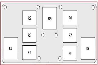
Additional relay blocks
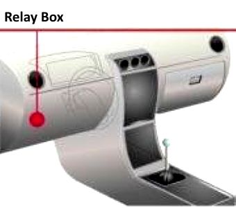
Located next to the main unit.
| Diagram | |
|---|---|
| Relay box (Type 1 - from 06/2009) | |
|
|
| 1 | No information |
| 2 | |
| 3 | |
| 4 | |
| R1 | Terminal 15 supply relay |
| R2 | Heated rear window relay |
| R3 | Horn relay |
| R4 | Headlight washer relay |
| R5 | Not used |
| R6 | |
| Relay box (Type 2 - up to 05/2009) | |
|
|
| R1 | Terminal 15 supply relay |
| R2 | Not used |
| R3 | |
| R4 | Terminal 30 supply relay |
| R5 | Heated rear window relay |
| R6 | Horn relay |
| R1 | not used |
| R8 | Headlight washer relay |
| R9 | not used |
| Additional fuse box | |

|
|
| 1 | - |
| 2 | - |
| 3 | Driver's seat adjustment 20A |
| 4 | - |
| R1 | Not used |
| R2 | cigarette lighter relay |
| R3 | Control relay |
| R4 | - |
| R5 | heating relay |
| R6 | - |
| R1 | terminal 50 supply voltage relay |
| R8 | no information |
| R9 | windshield convertible relay |
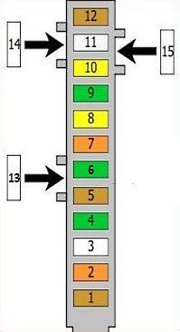
In the trunk

Under the casing on the right is an additional relay box. Near the battery there is a power module consisting of high-power fusible links.
| Relay block diagram | ||
|---|---|---|
|
||
| No. | Description | A |
| 1 | Power control unit | 5 |
| 2 | 40 | |
| 3 | empty | - |
| 4 | Hydraulic pump, convertible roof. | |
| 5 | Parking assistant controller; | 5 |
| 6 | Fuel pump control module | 50 |
| 7 | Power control unit | 40 |
| 8 | ABS control unit | 20 |
| 9 | Electronic Throttle Control Unit | 30 |
| 10 | Comfort system control unit; | 10/20 |
| Power control unit | ||
| 11 | convertible roof | 25 |
| 12 | Comfort control unit | 5 |
| 13 | empty | |
| 14 | empty | |
| 15 | empty | |
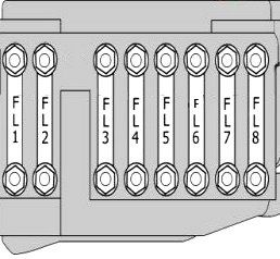
Power fuses
Located near the battery.
| diagram | ||
|---|---|---|
|
||
| No. | Description | A |
| FL1 | Generator | 175 |
| FL2 | Power steering control unit | 80 |
| FL3 | Radiator fan controller; | 60 |
| FL4 | Fuse and relay box in the engine compartment | 110 |
| FL5 | secondary air pump | 40 |
| FL6 | empty | - |
| FL7 | empty | - |
| FL8 | empty | - |
