E39 is a body modification of the BMW "fifth" series, which was produced from 1995 to 2004 inclusive. The base model in the family was the 520i. Its two-liter engine had 150 hp of power, and after restyling the volume increased to 2.2 liters, and the power to 170 hp. In this article, we will take a detailed look at the fuse box diagrams for the BMW E39 (5 series; 4th Gen; 520d, 520i, 523i, 525d, 525i, 528i, 530d, 535i, 540d, M5) 1995, 1996, 1997, 1998, 1998, 1999, 2000, 2001, 2002, 2003, 2004 years of manufacture.

Here you will find the locations and photos of distribution boxes. The fuses responsible for the “Cigarette lighter” and “Fuel Pump” are highlighted in bold.
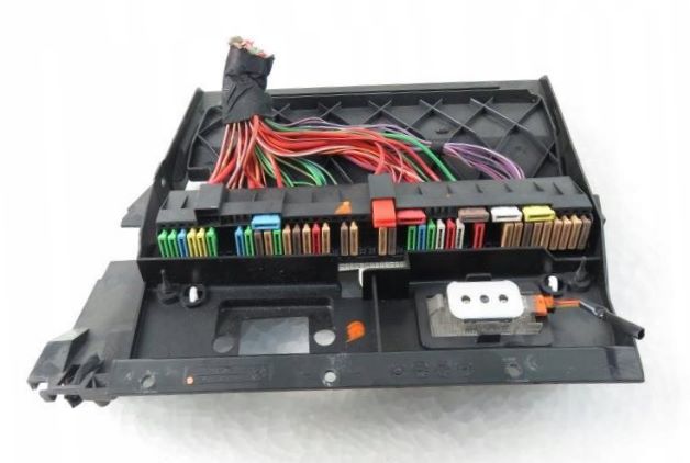
In the trunk
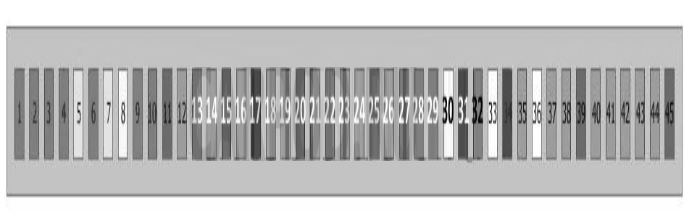
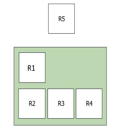
Main fuse box
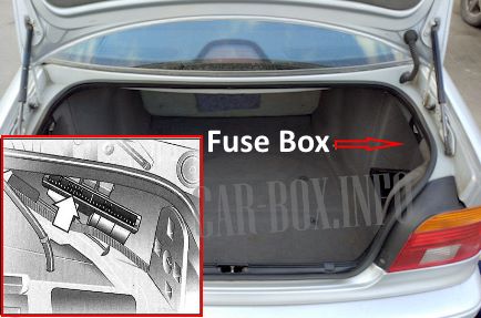
Located behind the right side trim.
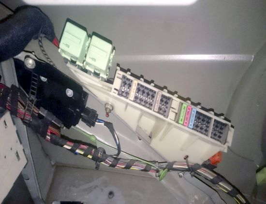
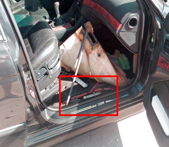
Access example.
| Diagram | ||
|---|---|---|
|
||
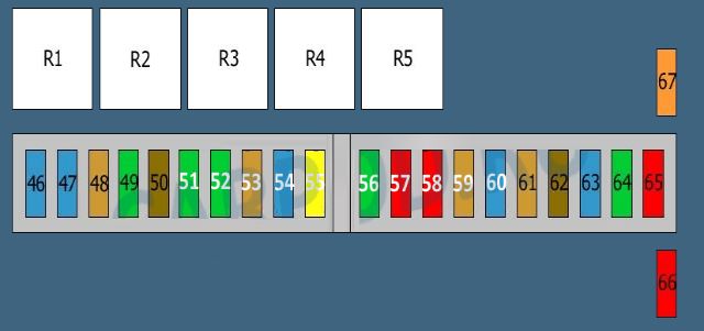
| Models before restyling | ||
| No. | Decryption | A |
| 46 | Independent heater/ventilation | 15 |
| 47 | Independent heater | 15 |
| 48 | Anti-theft system | 2 |
| 49 | air suspension | 30 |
| 50 | air suspension | |
| 51 | Active air suspension compressor (if equipped) | - |
| 52 | cigarette lighter fuse | 30 |
| 53 | central locking system | 7.5 |
| 54 | Fuel pump fuse | 15 |
| 55 | Rear windshield washers and wipers (if equipped) | - |
| 56 | Audio system, navigation system, trip computer | 30 |
| 57 | Phone | 10 |
| 58 | Audio system, trip computer, navigation system, telephone | 10 |
| 59 | Cigarette lighter relay (if equipped) | - |
| 60 | Suspension control system | 15 |
| 61 | Parking assistance system (if equipped) | - |
| 62 | Alarm sensor | - |
| 63 | Radio, anti-theft system | - |
| 64 | Radio | - |
| CD changer | ||
| Amplifier | ||
| On-board computer | ||
| video system | ||
| Navigation control unit | ||
| GPS system | ||
| 65 | Receiver / transmitter (if available) | |
| 66 | Rear window heater | 40 |
| 67 | Trunk lid control units (if available) | - |
| R1 | Main Ignition Relay | |
| R2 | Fuel pump relay | |
| R3 | Rear window heater relay | |
| R4 | Ignition Auxiliary Relay | |
| R5 | Independent heater relay or Fuel filler lock actuator relay | |
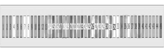
| Models after restyling | ||
| No. | Decryption | A |
| 46 | Empty | - |
| 47 | Additional heater | 15/20 |
| 48 | Auto-dimming interior rearview mirror, anti-theft control unit (with volume control), vehicle tilt sensor (anti-theft alarm), anti-theft alarm | 5 |
| 49 | Active Suspension Compressor Relay | 30 |
| 50 | Suspension control unit (with air suspension) | |
| 51 | Cigarette lighter - rear | 30 |
| 52 | Cigarette lighter relay, front cigarette lighter fuse | 30 |
| 53 | Antenna booster, trunk lid/tailgate lock switch | 5 |
| 54 | Fuel module relay (fuel pump) | 15 |
| 55 | Rear window wiper/washer relay | 20 |
| 56 | Audio system, navigation control unit, audio output amplifier, CD changer, multifunction display | 30 |
| 57 | Phone | 10 |
| 58 | Overload/Surge Protection Relay | 10 |
| 59 | Trailer electrical connector | 20 |
| 60 | Suspension control unit, multifunction switch | 15 |
| 61 | Left Rear Seat Heater Switch, Right Rear Seat Heater Switch | 25 |
| 62 | Anti-theft sensors | - |
| 63 | Radio | - |
| 64 | Connecting control box | - |
| 65 | Front Defroster Relay (If Equipped) | - |
| 66 | Rear defroster relay | 40 |
| 67 | Fuel filler lock relay (if equipped) | - |
| R1 | Relay 1 for overload/surge protection | |
| R2 | Fuel pump relay | |
| R3 | Rear defroster relay | |
| R4 | Overload/surge protection relay 2 | |
| R5 | Fuel filler lock relay | |
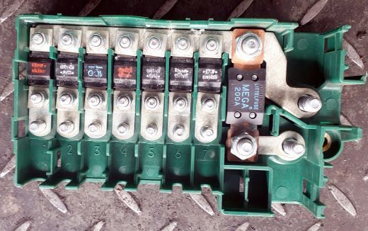
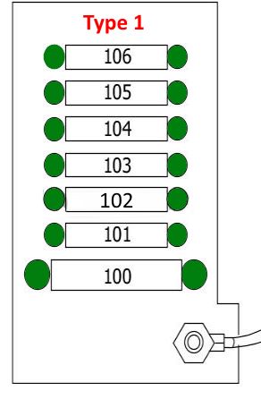
Power fusible links

The power block with fusible links is located above the battery.
| Diagram | ||
|---|---|---|
General view of the board. |
||
|
||
|
||
| No. | Decryption | Amps |
| 100 | Fuse box in the footwell (107-114) | 200 |
| 101 | Main unit in trunk | 80 |
| 102 | 80 | |
| 103 | Trailer control unit | 50 |
| 104 | Overload/surge protection relay 2 | 50 |
| 105 | Fuse box in passenger compartment, auxiliary heater | 100 |
| 106 | Main unit in trunk | 80 |
In the cabin
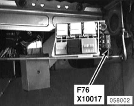
Main fuse box
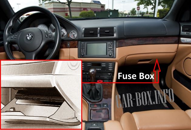
Located behind the glove compartment.
General view of the BMW e39 interior fuse box.
| Diagram | ||
|---|---|---|
| Models before restyling | ||
|
||
| No. | Decryption | Amps |
| 1 | windshield wiper | 30 |
| 2 | Headlight washers, windshield washers | 30 |
| 3 | Horn (beep) | 15 |
| 4 | Interior light bulbs, trunk light bulb, windshield wiper | 20 |
| 5 | sunroof | 20 |
| 6 | Power windows, power door mirrors, central locking system | 30 |
| 7 | AC condenser fan motor | 20 |
| 8 | Traction control | 25 |
| 9 | Air conditioning system, windshield heaters | 15 |
| 10 | Power Seat - Passenger Side | 30 |
| 11 | power steering | 7.5 |
| 12 | Immobilizer | 5 |
| 13 | Power Steering Column Adjustment, Power Seat - Driver's Side | 30 |
| 14 | Engine management | 5 |
| 15 | Engine management system, diagnostic connector | 7.5 |
| 16 | Lighting control unit | 5 |
| 17 | ABS system (diesel), traction control, bmw e39 fuel pump fuse | 10 |
| 18 | instrument cluster | 5 |
| 19 | Spare | 5 |
| 20 | Air conditioning/heating system, rear window heater, air conditioner condenser fan motor | 7.5 |
| 21 | Power driver's seat, parking system, garage door remote control system, interior rearview mirror, temperature sensor | 5 |
| 22 | Air conditioning condenser fan motor | 30 |
| 23 | Heater, independent heater | 10 |
| 24 | Instrument cluster, gear selector lamp | 5 |
| 25 | Multifunction display, audio system | 7.5 |
| 26 | windshield wiper | 5 |
| 27 | Power windows, central locking system | 30 |
| 28 | Heater fan motor, air conditioning system | 30 |
| 29 | Power windows, central locking, power door mirrors | 30 |
| 30 | ABS system | 25 |
| 31 | ABS system, traction control, fuel pump | 10 |
| 32 | seat heater | 15 |
| 33 | Empty | - |
| 34 | Steering wheel heater | 10 |
| 35 | Empty | - |
| 36 | Empty | - |
| 37 | Immobilizer | 5 |
| 38 | Beep (horn), diagnostic connector, transmission selector light | 5 |
| 39 | Vanity mirror light, charging port | 7.5 |
| 40 | SRS system, instrument cluster | 5 |
| 41 | Stop lights, lighting control unit, cruise control | 5 |
| 42 | Safety Airbag | 5 |
| 43 | On-board computer, audio system, telephone | 5 |
| 44 | Multifunction steering wheel controls, multifunction display, audio system, telephone | 5 |
| 45 | Sun Shade - Rear | 7.5 |
| Models after restyling | ||
|
||
| No. | Description | A |
| 1 | Windshield wiper motor relay | 30 |
| 2 | Headlight washers | 30 |
| 3 | Horn (beep) | 15 |
| 4 | Multifunction control box | 20 |
| 5 | Moonroof | 20 |
| 6 | Door Mirror Power Circuit Fuse, Passenger Side | 30 |
| 7 | Cigarette Lighter - Front (09/00^) | 20/30 |
| or | ||
| A/C condenser fan motor relay | ||
| 8 | Empty | - |
| 9 | Air conditioner/heater control unit | 15 |
| 10 | Power Seat - Passenger Side | 30 |
| 11 | Multifunction control unit - variable power steering | 7.5 |
| 12 | Immobilizer | 5 |
| 13 | Power Seat - Driver Side, Steering Column Adjuster | 30 |
| 14 | Electronic engine control unit | 5 |
| 15 | TCM, Engine Oil Level Sensor, Alternator, Mounting Block (Temperature Sensor) (530d) | 7.5 |
| 16 | Lighting control unit | 5 |
| 17 | Fuel Pump Relay, ABS ECU, Multifunction Switch | 10 |
| 18 | instrument cluster | 5 |
| 19 | Overload/surge protection relay 2 | 5 |
| 20 | A/C/Heater Control Module, Rear Defroster Relay, Tire Pressure Monitoring System Control Module | 5/7.5 |
| 21 | Cigarette lighter relay, power seat relay / steering column control relay, garage door remote control system, parking system control unit, auto-dimming interior rearview mirror | 5 |
| 22 | Fuel Pump Relay - 530d/520i (226S 1)/525i/530i | 25 |
| or | ||
| A/C condenser fan motor relay 2 | 30 | |
| 23 | Multifunction Display - Rear | 7.5 |
| 24 | Instrument cluster, tire pressure monitoring control unit, steering wheel position sensor | 5 |
| 25 | Multifunction display | 7.5 |
| 26 | Empty | - |
| 27 | Multifunction control box | 30 |
| 28 | automatic transmission | 15 |
| 29 | Door electrical control unit, driver's side | 30 |
| 30 | ABS electronic control unit | 25 |
| 31 | Fuel Pump Relay, ABS ECM, Exhaust Air Pump Relay (Gasoline) | 10 |
| 32 | Multifunction switch assembly | 25 |
| 33 | Empty | - |
| 34 | Multifunction steering wheel/airbag, steering wheel heater | 10 |
| 35 | A / C condenser fan motor, rear | 5 |
| 36 | Empty | - |
| 37 | Electronic immobilizer control unit | 5 |
| 38 | Multifunction control unit, horn relay, rain sensor, automatic transmission lock switch, diagnostic socket | 5 |
| 39 | Vanity mirror lights, rechargeable torch | 7.5 |
| 40 | Instrument Cluster, Power Seat Control Module, Crash Sensor (SRS), Driver Seat Belt Sensor | 5 |
| 41 | Lighting control unit, clutch pedal position sensor, brake light switch (brake pedal position sensor) | 5 |
| 42 | SRS electronic control unit | 5 |
| 43 | Relay 1 overload / overvoltage surge protection | 5 |
| 44 | Multifunction steering wheel/airbag, steering wheel, multifunction display - front/rear | 5 |
| 45 | Multifunction switch assembly | 7.5 |
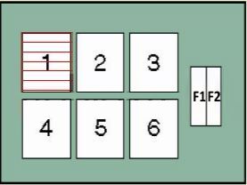
Additional relays
Behind the main fuse box in a special white box are additional relay modules.
| Diagram | ||
|---|---|---|
| Type 1 | ||
|
||
| No. | Purpose | Amps |
| F1 | Air conditioner condenser fan motor, cooling fan motor | 50 |
| F2 | Air conditioner/heater fan motor control unit | 40 |
| 1 | A/C condenser fan motor relay 2(^03/98) | |
| 2 | headlight washer pump | |
| 3 | empty | |
| 4 | starter | |
| 5 | Power Seat/Steering Column Adjuster Relay | |
| 6 | heater fan motor | |
| Type 2 | ||
|
||
| No. | Purpose | |
| 1 | Additional cooling fan, stage 2 | |
| 2 | Starter | |
| 3 | Trip relay | |
| 4 | Radiator Fan | |
| 5 | headlight washer | |
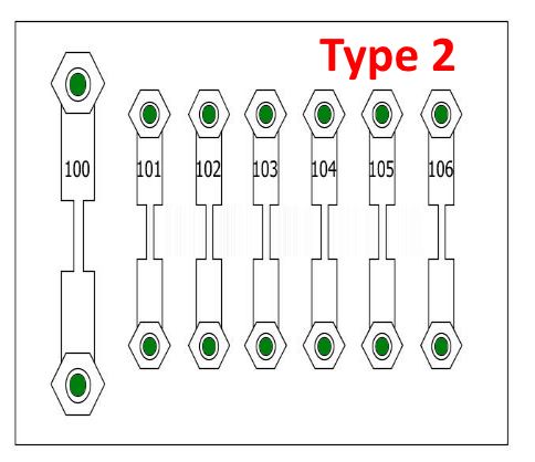
Power fusible links
Under the floor pan on the passenger side there is a power unit with fusible elements.
| Diagram | ||
|---|---|---|

|
||
| No. | Decryption | Amps |
| F107 | Secondary Air Injection Pump Relay (AIR) | 50 |
| F108 | ABS module | 50 |
| F109 | Engine control relay (EC), fuse box (F4 & F5) | 80 |
| F110 | Fuse Block - Fascia 1 (F1-F12 and F22-F25) | 80 |
| F111 | Ignition lock | 50 |
| F112 | Lamp control module | 80 |
| F113 | steering wheel / steering column position adjustment relay, fuse box fascia 1 (F27-F30), fuse box fascia 2 (F76), lamp control module, fuse box fascia 1 (F13) - with lumbar support | 80 |
| F114 | ignition switch, data line connector (DLC) | 50 |
In the engine compartment
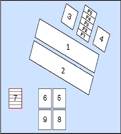
Fuse box
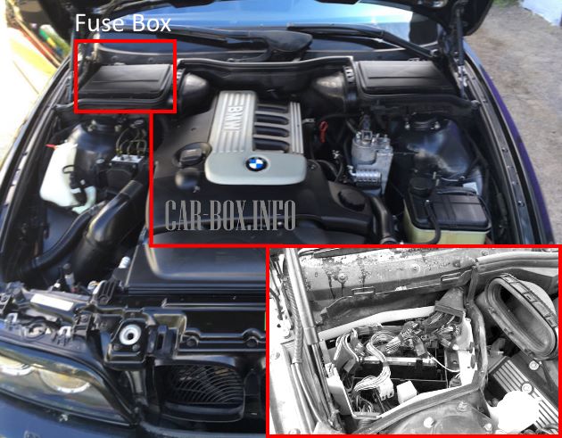
The distribution box is located closer to the windshield, in the corner behind the protective cover.
| Diagram | ||
|---|---|---|
|
||
| No. | Purpose of fuses | Amps |
| 1 | ECM, EVAP valve, air mass sensor, camshaft position sensor 1, coolant thermostat - 535i/540i | 30 |
| F2 | Exhaust air pump, intake manifold geometry modification e/m valve, injectors (except 520i (22 6S 1)/525i/530i), ECU, fuel vapor battery e/m valve, timing system actuator (1,2), idle speed control actuator. | 30 |
| F3 | Crankshaft position sensor, camshaft position sensor(1,2), air flow sensor | 20 |
| F4 | Heated oxygen sensors, electronic engine control unit | 30 |
| F5 | Ignition Coil Relay - Except 520i (22 6S1)/525i/530i | 30 |
| Relay - type 1 | ||
| 1 | Engine control module | |
| 2 | transmission control module | |
| 3 | Engine control module fuse | |
| 4 | Engine control module relay | |
| 5 | Wiper motor relay I | |
| 6 | Wiper Motor II | |
| 7 | A/C fan motor relay I | |
| 8 | A/C fan relay 3 | |
| 9 | ABS | |
| Relay - type 2 | ||
| 1 | Electronic engine control unit | |
| 2 | Electronic transmission control unit | |
| 3 | engine management systems | |
| 4 | ignition coils - except 520i (22 6S 1) /525i/530i | |
| 5 | Windshield wiper motor relay 1 | |
| 6 | Windshield wiper motor relay 2 | |
| 7 | A/C condenser fan motor relay 1 (^03/98) | |
| 8 | A/C condenser fan motor relay 3 (^03/98) | |
| 9 | exhaust air pump | |
Relays

Description.
- R1 - Wiper relay
- R2 - Additional cooling fan, stage 1
- R3 - Wiper No. 1
- R4 - Wiper No. 2
- R5 - Additional cooling fan, stage 3
- R6 - Glow plug relay (diesel)
- R7 - DDE relay
- R8 - Glow plug relay (diesel)
- R9 - DME relay
- R10 - Secondary air pump relay
- R11 - Unloader relay, terminal 15
- R12 - Fuel injectors or starter relay

Comprehensive.