
Table of Contents
The Chevrolet Epica V250 is a mid-size sedan produced from 2006 to 2013.

This guide provides information on all fuse and relay blocks for the Epica V250, including photos and the locations of the power distribution boxes.
Passenger Compartment
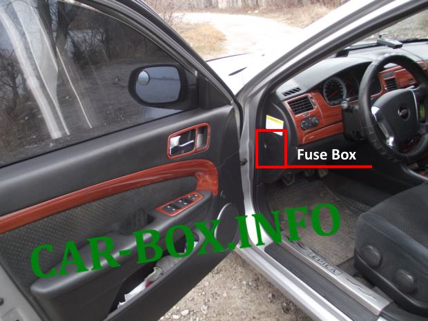
The passenger compartment fuse box is located on the left side of the instrument panel (dashboard).
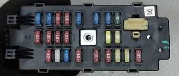
General view.
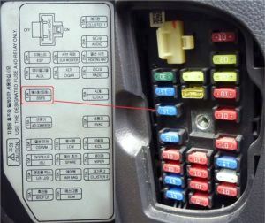
Access panel removed.
| Diagram | ||
|---|---|---|
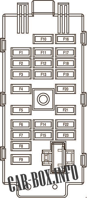
|
||
| No. | Amps | Description |
| F1 | 10 | Instrument cluster, information display, LCM, RKE module, TCM, Park/Neutral Position (PNP) switch |
| F2 | 25 | Wiper/washer switch, windshield wiper motor, rain sensor module |
| F3 | 50 | Unused |
| F4 | 10 | ISU, blower motor relay, MTC/FATC control module, mode door actuator, recirculation door actuator |
| F5 | 10 | Front courtesy light/sunroof switch, LCM, digital clock |
| F6 | 10 | Audio system, navigation module |
| F7 | 20 | Heated seat switch (driver/passenger) |
| F8 | 20 | Audio system |
| F9 | 10 | Instrument cluster, MTC/FATC control module, digital clock, information display, LCM, key-in ignition switch, RKE module |
| F10 | 10 | Heated rear window (HR) |
| F11 | 10 | Passenger airbag/seat belt warning indicator, Passenger Presence Detection (PPD) sensor |
| F12 | 10 | Spare |
| F13 | 10 | LCM |
| F14 | 20 | Accessory power outlet, cigarette lighter |
| F15 | 20 | Subwoofer |
| F16 | 50 | Shift lever, PNP switch, reverse light switch, electrochromic (ECM) rearview mirror, brake light switch, instrument cluster |
| F17 | 50 | Engine Control Module (ECM), fuel pump module, automatic transaxle, Mass Air Flow (MAF) sensor |
| F18 | 10 | ISU, wiper/washer switch |
| F19 | 10 | Power mirrors (driver/passenger), MTC/FATC control module |
| F20 | 50 | Unused |
| F21 | 50 | Speed Sensitive Power Steering (SSPS) module |
| F22 | 50 | Data Link Connector (DLC), trunk release switch |
| F23 | 30 | Electronic Brake Control Module (EBCM) |
Engine Compartment
Main Fuse Box
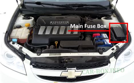
Located next to the coolant reservoir and battery, enclosed by a plastic cover.
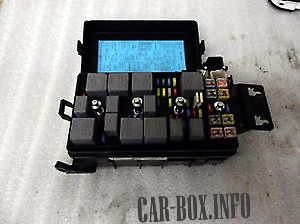
General view.
| Diagram | ||
|---|---|---|
|
||
| No. | Amps | Description |
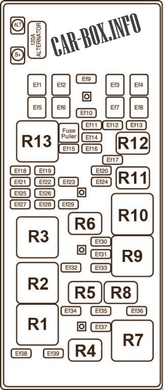
| Ef1 | 30 | Cooling fan relay |
| Ef2 | 60 | Integrated logic switch block |
| Ef3 | 60 | Electronic Brake Control Module (EBCM) |
| Ef4 | 30 | Ignition switch |
| Ef5 | 20 | Power window/driver door lock switch |
| Ef6 | 30 40 |
Cooling fan relay (high speed) |
| Ef7 | 20 40 |
Cooling fan relay (low speed) |
| Ef8 | 30 | Ignition switch, starter relay |
| Ef9 | 50 | Spare |
| Ef10 | 10 | Spare |
| Ef11 | 20 | Spare |
| Ef12 | 25 | Spare |
| Ef13 | 30 | Spare |
| Ef14 | 10 | Unused |
| Ef15 | 20 | Sunroof assembly |
| Ef16 | 50 | ECM, ABS hydraulic unit connector |
| Ef17 | 50 | Headlamps (left/right) |
| Ef18 | 20 | Power window safety module |
| Ef19 | 10 | Multifunction switch |
| Ef20 | 10 | Right headlamp, right parking lamp, right tail lamp |
| Ef21 | 30 | Lighting Control Module (LCM) |
| Ef22 | 25 | Instrument panel fuse box |
| Ef23 | 20 | Brake light switch |
| Ef24 | 10 | Left headlamp, left parking lamp, left tail lamp, license plate lamp |
| Ef25 | 30 | Power driver's seat switch |
| Ef26 | 20 | Fuel pump module |
| Ef27 | 50 | ECM, engine main relay, automatic transaxle |
| Ef28 | 20 | Gasoline: Ignition coils 1–6 Diesel: Unused |
| Ef29 | 50 | Horn relay |
| Ef30 | 50 | Gasoline: Fuel injectors 1–6, Vehicle Speed Sensor (VSS), EVAP canister purge solenoid Diesel: ECM, VSS, PTC 1/2/3 heater relays |
| Ef31 | 20 | ECM |
| Ef32 | - | - |
| Ef33 | 50 | Gasoline: EGR solenoid, alternator, ECM, VIM solenoid, oxygen sensor, CMP sensor, MAF sensor, EVAP canister vent solenoid Diesel: Boost control actuator, CMP sensor, throttle valve actuator, EGR solenoid, fuel filter heater relay, WIF sensor, glow plug controller |
| Ef34 | 50 | Front fog lamp relay |
| Ef35 | 10 | Left headlamp |
| Ef36 | 20 | Amplifier |
| Ef37 | 10 | Right headlamp, multifunction switch |
| Ef38 | - | - |
| Ef39 | 10 | A/C compressor relay |
| Relays | ||
| R1 | Cooling fan control relay | |
| R2 | Cooling fan relay (high speed) | |
| R3 | Fuel pump relay | |
| R4 | A/C compressor clutch relay | |
| R5 | Front fog lamp relay | |
| R6 | Horn relay | |
| R7 | Cooling fan relay (low speed) | |
| R8 | Low beam relay | |
| R9 | Main relay | |
| R10 | Starter relay | |
| R11 | Parking lamp relay | |
| R12 | High beam relay | |
| R13 | Power window relay | |
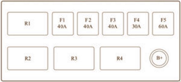
Auxiliary Fuse Box (Diesel Only)
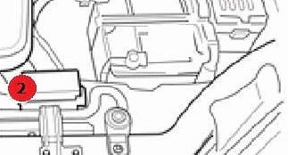
Sub-fuse box #2 is located in the engine compartment, next to the bulkhead (firewall).
| Diagram | |
|---|---|
|
|
| No. | Description |
| 1 | PTC auxiliary heater 3 |
| 2 | PTC auxiliary heater 2 |
| 3 | PTC auxiliary heater 1 |
| 4 | Fuel filter heater relay |
| F1 | (40A) Auxiliary heater |
| F2 | (40A) Auxiliary heater |
| F3 | (40A) Auxiliary heater |
| F4 | (30A) Fuel filter heater |
| F5 | (60A) Glow plugs |
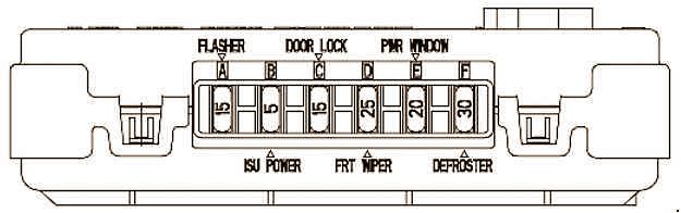
Integrated Logic Switch Block
Diagram.
|
||
| No. | Amps | Description |
| A | 50 | Circuit breaker |
| B | 5 | Integrated logic switch block power |
| C | 50 | Door locks |
| D | 25 | Front wipers |
| E | 20 | Power windows |
| F | 30 | Rear window defogger |
