The main part of the power supply circuits of the electrical equipment of the American elevator (hybrid) is protected by fuses. Powerful current consumers are connected via relays. Protective elements are installed in the cabin and engine compartment, as well as in the trunk.

The information provided in the diagrams is relevant for 1st generation Chevrolet Volt models of 2010, 2011, 2012, 2013, 2014, 2015.
In the luggage compartment
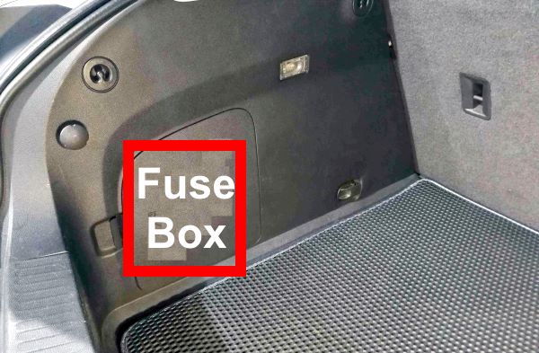
The fuse and relay box is located on the left side of the trunk, behind the trim.
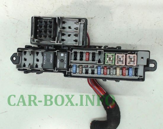
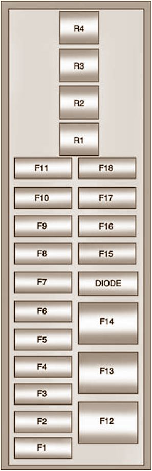
General view.
| Diagram | ||
|---|---|---|
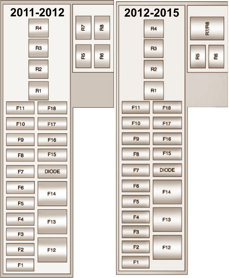
|
||
| № | Amps | Description |
| F1 | - | Not used |
| F2 | 15 | K27 Fuel pump control module |
| F3 | 10 | K84 Keyless entry control module |
| F4 | 25 | K29 Heated seat control module (if equipped) |
| F5 | 20/2 | S52 Outside rearview mirror switch, S79D Window switch - driver, S113 Charge connector cover release switch, S117 Refuel command switch |
| F6 | 10 | Q13 EVAP canister valve, Q63 EVAP canister leak detection pump unit |
| F7 | 15 | G38 Cooling fan for power module 14 V |
| F8 | 20 | T3 Audio amplifier (if equipped) |
| F9 | 10 | 2011-2012, 2014-2015: Not used 2013: Digital audio broadcasting (if equipped) |
| F10 | 5 | K9 Body control module, K41 Parking aid control module (if equipped) |
| F11 | 15 | KR3 Horn relay |
| F12 | 30 | S79LR Power Window Switch - Left Rear, S79RR Power Window Switch - Right Rear |
| F13 | 30 | K83 Parking brake control module |
| F14 | 40 | E18A Rear defogger grill - upper |
| F15 | - | Not used |
| F16 | 10 | A23C Tailgate latch block |
| F17 | - | Not used |
| F18 | - | Not used |
| DIOD | - | Not used |
| Relay | ||
| R1 | 40 | Relay, rear defogger |
| R2 | 20 | Rear tailgate lock release relay |
| R3 | 20 | Not used |
| R4 | 20 | Not used |
| R5 | - | Not used |
| R6 | - | Not used |
| R7 R8 |
- | Horn relay |
| R7 | - | Not used |
| R8 | - | P12L Sound signal - left, P12R Sound signal - right |
In the passenger compartment
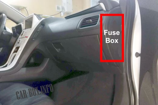
Fuse box #1
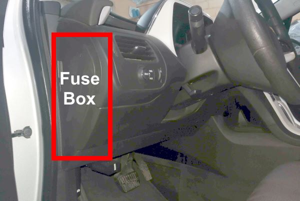
Located on the driver's side at the end of the dashboard.
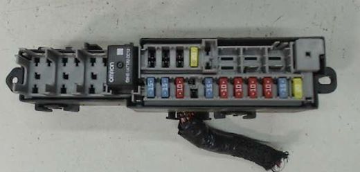
Photo - example.
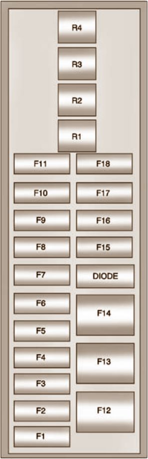
| Diagram | ||
|---|---|---|
|
||
| № | Amps | Description |
| F2 | 15 | A11 Radio receiver |
| F3 | 10 | P16 dashboard |
| F4 | 10 | P17 Information Display Module |
| F5 | 10 | A20 Audio / Climate Controls, K33 Heating, Ventilation and Air Conditioning Control Module |
| F6 | 10 | K36 Airbag sensor and diagnosis module, K85 Passenger occupancy detection module |
| F7 | 15 | X84 Diagnostic connector, X84B Additional diagnostic connector |
| F8 | ** | 2011-2012, 2014-2015: Not used 2013: Column lock (LHD) |
| F9 | 10 | 2011: Not used 2012-2015: OnStar |
| F10 | 15 | K9 body control module (according to manual X1 ) |
| F11 | 15 | K9 body control module ( X4 manual ) |
| F12 | ** | 2011-2012, 2014-2015: Not used 2013: Fan (RHD) (if equipped) |
| F13 | - | Not used |
| F14 | - | Not used |
| F15 | 20 | X80H Bodywork Power Socket - Center Console |
| F16 | — | Not used |
| F17 | - | Not used |
| F18 | - | Not used |
| DIODE | - | Not used |
| Relay | ||
| R1 | - | RAP RELAY |
| R2 | - | Not used |
| R3 | - | Not used |
| R4 | - | 2011-2012, 2014-2015: Not used 2013: Lock (if equipped with LHD) / Childproof lock (RHD) |
Fuse box #2
An additional distribution box is located at the passenger side of the instrument panel.
| Diagram | ||
|---|---|---|
|
||
| №. | Amps | Description |
| F1 | 2 | S70L Combined steering wheel switch - left, S70R Combined steering wheel switch - right |
| F2 | 10 | 2011-2012, 2014-2015: Not used 2013: Column lock (RHD) |
| F3 | - | Not used |
| F4 | 15 | K9 body control module (X3) |
| F5 | 15 | K9 Body Control Module (X2) |
| F6 | 15 | K9 Body Control Module (X5) |
| F7 | 15//7.5 | K9 Body Control Module (X6) |
| F8 | 15 | K9 Body Control Module (X7) |
| F9 | 20 | K9 Body Control Module (X8) |
| F10 | 10/15 | K73 Telematic communication interface control module |
| F11 | 7.5 | S25 Garage door opener |
| F12 | 30 | K8 Fan control module |
| F13 | - | Not used |
| F14 | - | Not used |
| F15 | - | Not used |
| F16 | - | Not used |
| F17 | - | Not used |
| F18 | - | Not used |
| DIOD | - | Not used |
| Relay | ||
| R1 | - | Not used |
| R2 | - | Not used |
| R3 | - | Not used |
| R4 | - | 2011: Not used 2012, 2014-2015: Childproof lock relay 2013: Childproof lock (if equipped with RHD), childproof lock (LHD) |
In the engine compartment
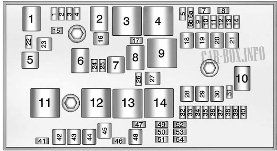
Main fuse box
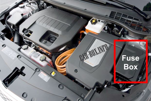
Located on the driver's side behind a protective cover.
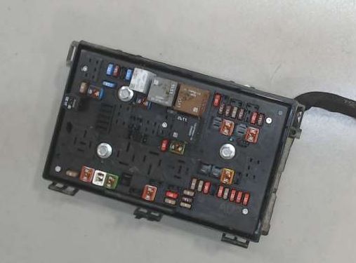
General view.
| Diagram | ||
|---|---|---|
|
||
| № | Amps | Description |
| Circuit breakers | ||
| 1 | 15 | K20 Engine control module |
| 2 | 10/7.5 | B52A Heated oxygen sensor 1, B52B Heated oxygen sensor 2, B75B MAF / IAT sensor, E41 Engine cooling thermostat heater, Q12 EVAP canister purge valve |
| 3 | 10 | 2011-2015: Not used (according to manual) Q17A Fuel injector 1, Q17B Fuel injector 2, Q17C Fuel injector 3, Q17D Fuel injector 4 (according to TIS) |
| 4 | 15 | K35 Ignition coil module |
| 5 | 10 | Not used |
| 6a | - | Not used |
| 6b | 10/7.5 | E18B Rear defogger grille - lower |
| 7 | - | Not used |
| 8 | - | Not used |
| 9 | 10/7.5 | E17D Outside rearview mirror glass - driver's side, E17P Outside rearview mirror glass - passenger side |
| 10 | 5 | G1 Air conditioning compressor |
| 11 | 10/7.5 | T6 Power inverter module |
| 12 | 15 | 2011 : G36 Coolant pump for auxiliary heater, Q66 Coolant regulation valve for passenger compartment heater |
| 13 | 10/7.5 | 2012-2015: G36 Auxiliary heater coolant pump, Q66 Passenger compartment heater coolant control valve |
| 14 | 10/7.5 | 2011-2012, 2014-2015: Not used (according to manual) 2013: Anti- theft device - Sounder (if equipped) (according to manual) |
| 15 | 15 | K71 Transmission control module, T6 Power inverter module |
| 16 | 20 | 2011, 2013: Not used 2012, 2014-2015: AIR solenoid (PZEV only) (if equipped) (manual) |
| 17 | 5 | K20 Engine control module |
| 18 | - | Not used |
| 19 | 30 | M74D Power Window Motor - Driver Side S79P Power Window Switch - Passenger Side |
| 20 | - | Not used |
| 21 | 40/30 | K17 Electronic brake control unit ABS MDL |
| 22 | 5 | M28L High beam adjustment solenoid valve actuator - left |
| 23 | 20 | KR113 Charging port door relay |
| 24 | - | Not used |
| 25 | - | Not used |
| 26 | 10 | 2011-2012, 2014-2015: Not used (according to manual) 2013: Anti- theft device - Buzzer (if equipped) (according to manual) |
| 27 | 50/60 | 2011, 2013: Not used 2012, 2014-2015: Air pump (PZEV only) (if equipped) (according to manual) |
| 28 | - | Not used |
| 29 | - | Not used |
| 30 | 60 | K17 Electronic brake control unit ABS MTR |
| 31 | 10 | 2011: G37 Hybrid Battery Pack Coolant Pump (according to manual) 2012-2015: Not used (according to manual) |
| 32 | 5 | K36 airbag diagnostic and monitoring module |
| 33 | 5 | K27 Fuel pump control module, K114B Hybrid powertrain control module 2 |
| 34 | 10 | K114B Hybrid powertrain control module 2 |
| 35 | 10 | 2011: G35 Hybrid electronic unit coolant pump (according to manual) 2012-2015: Not used (according to manual) |
| 36 | 10 | 2011: Not used (according to manual) 2012-2015: G35 Hybrid electronic unit coolant pump (according to manual) |
| 37 | 5 | K10 Heater control module on coolant |
| 38 | 10 | 2011: Not used (manual) 2012-2015: A4 Hybrid battery pack, A28 Hybrid battery contactor box, Coolant pump (manual) |
| 39 | 10 | A4 HV battery pack, A28 Hybrid battery contactor box, K16 Battery energy management module |
| 40 | 10 | KR11 Windshield washer pump relay |
| 41 | 5 | M28R High beam adjustment solenoid valve actuator - right |
| 42 | 30 | G10R Cooling Fan Motor - Right |
| 43 | 25 | M75 Windshield wiper motor |
| 44 | 40 | T18 Battery charger |
| 45 | - | Not used |
| 46 | - | Not used |
| 47 | - | Not used |
| 48 | 30 | G10L Cooling Fan Motor - Left |
| 49 | - | Not used |
| 50 | 10 | B87 Rear view camera |
| 51 | 5 | A4 Hybrid Powertrain Battery Pack, K16 Battery Energy Management Module, K17 Electronic Brake Control Module, T18 Battery Charger |
| 52 | 5 | K20 Engine control module, Q8 Control solenoid valve assembly |
| 53 | 10 /7.5 | T6 Power inverter module |
| 54 | 5 | G1 A / C Compressor, K1 14V Power Module, P14 Passenger Airbag Disabled Indicator, P16 Instrument panel |
| Relay | ||
| 1 | - | Not used |
| 2 | - | AIR SOL If equipped |
| 3 | - | PWR/TRN |
| 4 | - | REAR DEFOG - Fuses F6UA, F9UA |
| 5 | - | 2011-2013: M80 Charging port door drive 2014-2015: Not used |
| 6 | - | Not used |
| 7 | - | Not used |
| 8 | - | Not used |
| 9 | - | If equipped AIR PUMP |
| 10 | - | Not used |
| 11 | - | Not used |
| 12 | - | Not used |
| 13 | - | Not used |
| 14 | - | STROKE / TURN - Fuses F32UA, F33UA, F50UA, F51UA, F52UA, F53UA, F54UA |
Auxiliary fuse box
Diagram.

|
||
| № | Amps | Description |
| 1 | 80 | Providing charging |
| 2 | 80 | K43 Power steering control module |
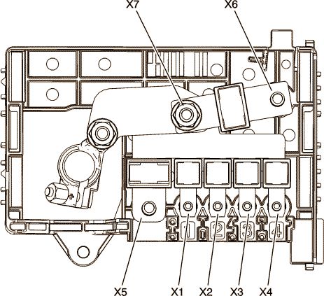
Power fuse panel
Located on the battery.
| Diagram | ||
|---|---|---|
|
||
| № | Amps | Description |
| 1 | 80 | X51L Fuse Box - Instrument Panel Left |
| 2 | 80 | X51R Fuse box - instrument panel, right |
| 3 | 80 | X53A Fuse Box - Trunk |
| 4 | 100 | Not used |
| - | 150 | X50B Fuse box - Additional auxiliary box in the engine compartment |
| - | 200 | Battery C1 |
