
Table of Contents
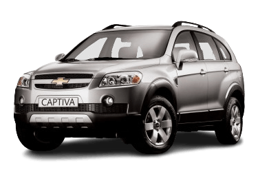
The Chevrolet Captiva entered the market in 2006 under the chassis designation C100, with production continuing through 2010. Following this period, the vehicle underwent a comprehensive facelift and platform update, resulting in the new chassis designation C140.
The specific fuse block diagram is located on the back of the fuse box cover. Please refer to it for the exact layout.
Engine Compartment
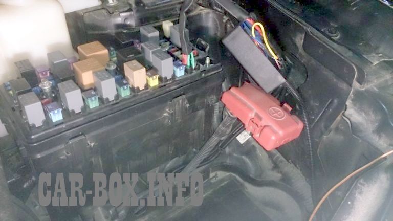
The fuse box is located next to the windshield washer fluid reservoir and is protected by a plastic cover.
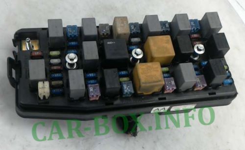
Reference image.
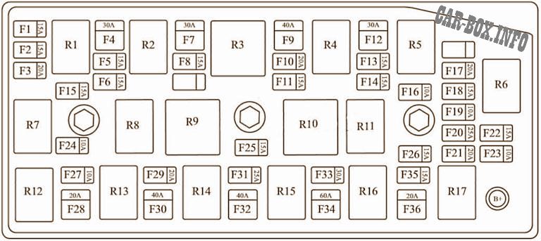
| Diagram | |
|---|---|
|
|
| No. | Description |
| F1 | Engine management |
| F2 | Engine management |
| F3 | Electronic Control Unit (ECU) |
| F4 | Main cooling fan |
| F5 | Fuel pump |
| F6 | All-Wheel Drive (AWD)* |
| F7 | Auxiliary relay |
| F8 | Brake lamps |
| F9 | Air conditioning / Ignition 1 |
| F10 | Sunroof* |
| F11 | Anti-theft system / Immobilizer |
| F12 | Rear window defogger |
| F13 | Left low beam headlamp |
| F14 | Right low beam headlamp |
| F15 | Engine management 3 |
| F16 | Left parking lamps |
| F17 | Headlamp washer |
| F18 | Transmission Control Module (TCM) |
| F19 | Right parking lamps |
| F20 | Spare |
| F21 | Spare |
| F22 | Spare |
| F23 | Spare |
| F24 | A/C compressor clutch |
| F25 | Horn |
| F26 | Front fog lamps |
| F27 | Main fuse |
| F28 | Starter motor |
| F29 | Anti-lock Braking System (ABS) |
| F30 | Anti-lock Braking System (ABS) |
| F31 | Windshield wipers |
| F32 | Start |
| F33 | Power seats |
| F34 | Battery |
| F35 | High beam headlamps |
| F36 | Rear window wiper |
| R1 | Auxiliary cooling fan relay |
| R2 | Fuel pump relay |
| R3 | Wiper speed control relay |
| R4 | Rear window defogger relay |
| R5 | High/low beam relay |
| R6 | Headlamp washer relay |
| R7 | Main relay |
| R8 | Main cooling fan relay |
| R9 | Cooling fan control relay |
| R10 | Cooling fan relay |
| R11 | Parking lamp relay |
| R12 | Starter relay |
| R13 | A/C compressor relay |
| R14 | Horn relay |
| R15 | Windshield wiper relay |
| R16 | Front fog lamp relay |
| R17 | High beam headlamp relay |
Passenger Compartment
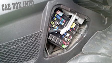
Inside the cabin, the fuse box is located on the left side of the passenger footwell and is concealed by a protective cover.

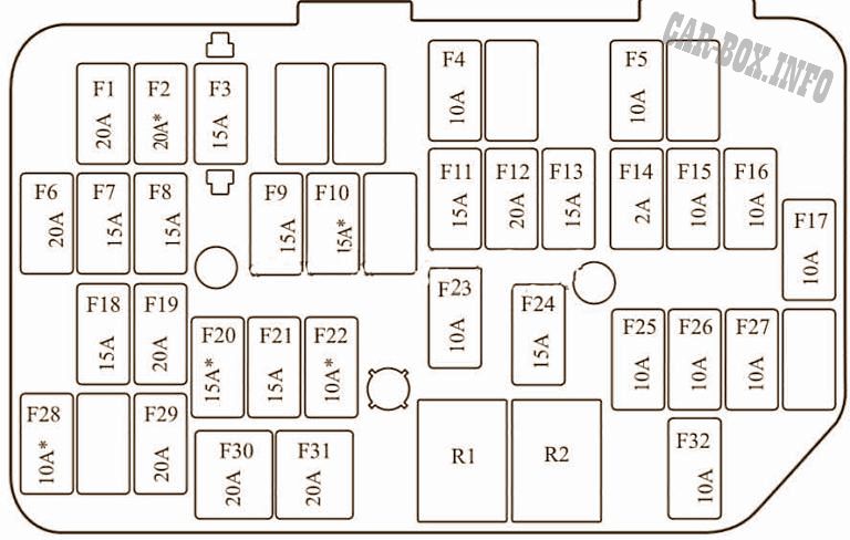
Overview.
| Diagram | |
|---|---|
|
|
| No. | Description |
| F1 | Auxiliary power outlet 1 |
| F2 | Heated front seats |
| F3 | Audio system |
| F4 | Air conditioning |
| F5 | Body Control Module (BCM) |
| F6 | Power door locks |
| F7 | Right turn signal |
| F8 | Left turn signal |
| F9 | Brake lamps |
| F10 | Headlamp washers |
| F11 | Air conditioning |
| F12 | Body Control Module (BCM) |
| F13 | Body Control Module (BCM) |
| F14 | Ignition switch |
| F15 | Rear fog lamps |
| F16 | Supplemental Restraint System (SRS) / Airbag |
| F17 | Windshield washer |
| F18 | Front power door locks |
| F19 | Auxiliary power outlet |
| F20 | Transmission Control Module (TCM) |
| F21 | Engine management |
| F22 | Low beam headlamps |
| F23 | Power windows |
| F24 | Heated exterior mirrors |
| F25 | Instrument cluster |
| F26 | Ignition 1 |
| F27 | Supplemental Restraint System (SRS) / Airbag |
| F28 | Power folding mirrors* |
| F29 | Cigarette lighter |
| F30 | Power window (passenger side) |
| F31 | Power window (driver side) |
| F32 | Clock |
| R1 | A/C relay / Auxiliary power outlet |
| R2 | Ignition: ON/START |