Table of Contents
Most of the electrical circuits of the American sedan are protected by fuses. Powerful consumers are connected via relays. Most of the protective elements are located in distribution boxes in the passenger compartment and under the hood.

The information provided in the diagrams is relevant for Chevrolet Aveo 2nd generation (T300) 2011, 2012, 2013, 2014, 2015 model year.
In the engine compartment

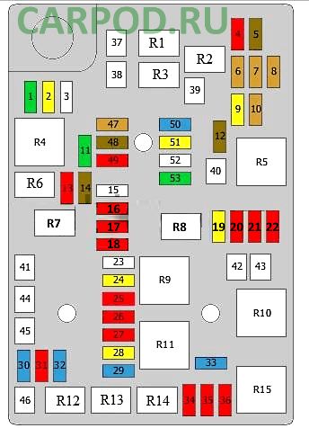
The distribution box is located on the left side of the engine compartment.
| Diagram (Type 1) | ||
|---|---|---|
|
||
| No. | Relay assignment | |
| R1 | Wiper | |
| R2 | Not used | |
| R3 | Wiper motor | |
| R4 | Rear windshield defroster relay | |
| R5 | Ignition | |
| R6 | Not used | |
| R7 | Relay, auxiliary coolant pump | |
| R8 | Relay fuel pump Aveo | |
| R9 | Not used | |
| R10 | Cooling fan, high speed | |
| R11 | Ignition relay 2 | |
| R12 | Starter | |
| R13 | A / C Compressor Clutch Relay | |
| R14 | High beam headlamp | |
| R15 | Cooling fan, low speed | |
| No. | Description of fuses | Amps |
| 1 | Electronic Brake Control Module (EBCM) | 30 |
| 2 | Sunroof | 20 |
| 3 | Not used | 25 |
| 4 | Not used | |
| 5 | Not used | |
| 6 | Not used | |
| 7 | Not used | |
| 8 | Body control unit | 5 |
| 9 | Rear wiper relay | 20 |
| Or | ||
| Rear wiper relay and motor | ||
| 10 | Battery gauge | 5 |
| 11 | Heated rear window | 30 |
| 12 | No | |
| 13 | ||
| 14 | Mirror control unit | 7.5 |
| 15 | Seat heating control unit | 25 |
| 16 | Fuel pump control unit | 10 |
| 17 | Canister purge solenoid | 10 |
| 18 | Rear washer pump | 10 |
| Windshield washer pump | ||
| 19 | Fuel module (fuel pump) | 20 |
| 20 | The engine control unit | 10 |
| 21 | Headlight adjustment actuators | 10 |
| Fuel pump control unit | ||
| 22 | Brake servo vacuum switch | 10 |
| Automatic transmission automatic transmission | ||
| Ignition transformer | ||
| 23 | No | |
| 24 | The engine control unit | 20 |
| 25 | Cooling fan, low speed relay | 10 |
| Cooling fan, fast relay | ||
| A / C Compressor Clutch Relay | ||
| Relay, auxiliary coolant pump | ||
| 26 | Air mass meter with air temperature sensor | 10 |
| Thermostat heater | ||
| 27 | Heated oxygen sensor 1 | 10 |
| Heated oxygen sensor 2 | ||
| 28 | The engine control unit | 20 |
| 29 | Injectors (cylinders 1 - 4) | 15 |
| Ignition coil | ||
| 30 | The engine control unit | 10 |
| 31 | A / C Compressor Clutch Relay | 10 |
| 32 | Transmission control unit | 15 |
| 33 | Signal | 15 |
| 34 | Front fog lights | 10 |
| 35 | Left high beam headlamp | 10 |
| 36 | High beam headlight, right | 10 |
| 37 | Wiper relay | 30 |
| 38 | Electronic Brake Control Module (EBCM) | 40 |
| 39 | Fan motor relay | 40 |
| 40 | Dashboard | 30 |
| 41 | No | |
| 42 | Cooling fan, high speed | 30 |
| 43 | Cooling fan, low speed | 40 |
| 44 | No | |
| 45 | ||
| 46 | Starter relay | 25 |
| 47 | Spare | 5 |
| 48 | Spare | 7.5 |
| 49 | Spare | 10 |
| 50 | Reserve | |
| 51 | Reserve | |
| 52 | Reserve | |
| 53 | Reserve | |
| Diagram (Type 2) | ||
|---|---|---|

|
||
| No. | Description | A |
| 1 | ABS / ESP system | 30 |
| 2 | Sunroof | 20 |
| 3 | - | |
| 4 | Rear window wiper motor | 20 |
| 5 | Multifunctional control unit | 15 |
| 6 | - | |
| 7 | - | |
| 8 | Power mirrors | 7.5 |
| 9 | - | |
| 10 | Heated rear window | 30 |
| 11 | - | |
| 12 | Power mirrors | 7.5 / 15 |
| 13 | Seat heater | 25 |
| 14 | Fuel pump control unit | 20 |
| 15 | - | |
| 16 | Rear washer pump | 10 |
| Windshield washer pump | 10 | |
| 17 | Engine management, fuel pump relay | 20 |
| 18 | Electronic engine control module (ECM) | 10 |
| 19 | Fuel pump control unit | 10 |
| Headlight adjustment actuators | ||
| 20 | Fuel pressure sensor | 10 |
| Automatic transmission | ||
| or not used | ||
| 21 | Canister purge solenoid | 10 |
| EGR valve | ||
| Intake manifold valve motor | ||
| Intake Manifold Adjustment Valve | ||
| 22 | Ignition coil | 10/20 |
| Ignition coils 1 - 4 | ||
| Cooling fan, low speed relay | ||
| Cooling fan, fast relay | ||
| A / C Compressor Clutch Relay | ||
| 23 | Air mass meter with air temperature sensor | 10 |
| Thermostat heater | ||
| The engine control unit | ||
| 24 | Heated oxygen sensor 1 | 10 |
| Heated oxygen sensor 2 | ||
| The engine control unit | ||
| Intake Manifold Adjustment Valve | ||
| 25 | Electronic engine control module (ECM) | 20 |
| 26 | Engine management (injectors (cylinders 1 - 4)) | 15 |
| 27 | Electronic engine control module (ECM) | 15 |
| 28 | Air conditioner / heater | 10 |
| 29 | Automatic transmission | 15 |
| Air vent solenoid | ||
| or not | ||
| 30 | Sound signal | 15 |
| 31 | Fog lights | 10 |
| 32 | High beam left headlight | 10 |
| 33 | High beam, right headlight | 10 |
| 34 | ABS / ESP system | 40 |
| 35 | Windshield wiper | 30 |
| 36 | Cooling fan motor | 40 |
| 37 | Passenger compartment fuse / relay box | 30 |
| 38 | - | |
| 39 | Cooling fan motor | 40 |
| 40 | 30 | |
| 41 | ABS / ESP system | 30 |
| 42 | Starter | 25 |
| 43 | Reserve | 5 |
| 44 | Reserve | |
| 45 | Reserve | 10 |
| 46 | Reserve | 15 |
| 47 | Reserve | 20 |
| 48 | Reserve | 25 |
| 49 | Reserve | 30 |
| R1 | Wiper relay | |
| R2 | Wiper motor relay | |
| R3 | Heated rear window relay | |
| R4 | Relay for main ignition circuits | |
| R5 | - | |
| R6 | Fuel pump relay 1 | |
| R7 | ||
| R8 | Engine control relay | |
| R9 | Starter relay | |
| R10 | A / C compressor electromagnetic clutch relay | |
| R11 | Headlamp high beam relay | |
| R12 | Cooling fan, low speed | |
| R13 | Fuel pump relay 2 | |
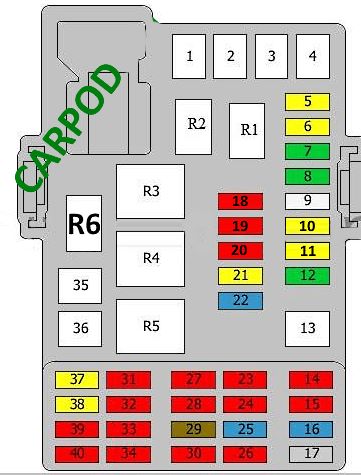
In the passenger compartment

The fuse box is located on the driver's side of the dashboard, behind a plastic cover.
| Diagram | ||
|---|---|---|
|
||
| No. | Description | A |
| 1 | Fuel heater | 40 |
| 2 | 60 | |
| 3 | - | |
| 4 | DC / DC converter control unit | 30 |
| 5 | Multifunctional body control module | 20 |
| 6 | 20 | |
| 7 | 30 | |
| 8 | 30 | |
| 9 | 25 | |
| 10 | 20 | |
| 11 | 20 | |
| 12 | 30 | |
| 13 | - | |
| 14 | Tailgate / tailgate opening drive | 10 |
| 15 | SRS system | 10 |
| 16 | Diagnostic connector | 15 |
| 17 | Egnition lock | 2 |
| 18 | Air conditioner electronic control unit | 10 |
| 19 | - | |
| 20 | Telematics | 10 |
| 21 | - | |
| 22 | Audio system | 15 |
| 23 | - | |
| 24 | Parking system control unit | 10 |
| 25 | - | |
| 26 | Instrument cluster | 10 |
| 27 | SRS system | 10 |
| 28 | Passenger airbag deactivation indicator | 10 |
| Dashboard | ||
| 29 | Clutch pedal limit switch (position sensor) | 7.5 |
| 30 | Headlights | 10 |
| 31 | - | |
| 32 | Air conditioner electronic control unit | 10 |
| 33 | - | |
| 34 | - | |
| 35 | Power windows (front) | 25 |
| 36 | Power windows (driver) | 25 |
| 37 | - | |
| 38 | Cigarette lighter fuse Aveo 300 | 20 |
| 39 | Sunroof | 10 |
| 40 | - | |
| R1 | Logistic mode relay 1 | |
| or | ||
| not used | ||
| R2 | Signal relay | |
| or | ||
| not used | ||
| R3 | Trunk / tailgate release relay | |
| R4 | - | |
| R5 | Heater blower motor relay | |
| R6 | Bodywork relay | |
View and print PDF:
