Chevrolet Cruze (J300) sales all over the world started in 2008. It was produced in 2009. 2010, 2011, 2012. After restyling in 2012, was released an updated model in 2013, 2014, 2015. In this article, we will take a detailed look at the fuse diagrams for the Cruze J300 with photos and locations of distribution boxes. The fuse responsible for the “Cigarette lighter” is highlighted in bold.

In the passenger compartment
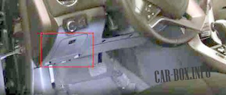
The fuse box is located in the panel on the left side right next to the driver's left knee. To access, you need to open the glove box for small items and pull it up. Then you should take the bottom of the box out of the panel stops and pull it out.

Example photo.
| Diagram | |
|---|---|
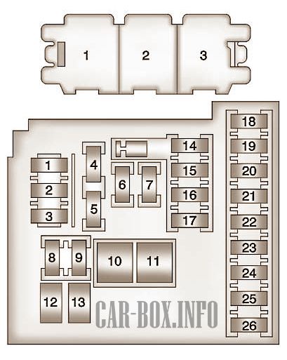
|
|
| No. | Apms / Description |
| 1 | 10A Mobile phone control module |
| 2 | Not used |
| 3 | 25A Body controller |
| 4 | 20A Radio receiver |
| 5 | 7.5A Parking aid control module, sound emitter, steering column switch - center console, display |
| 6 | 20A Cigarette lighter - front |
| 7 | 20A Socket for additional electrical appliances - center console 1/2 |
| 8 | 30A Body controller |
| 9 | 30A Body controller |
| 10 | 30A Body controller |
| 11 | 40A Door control module - Electric fan |
| 12 | Not used |
| 13 | 25A Seat heating control system module |
| 14 | 7,5A Diagnostic block, oil supply connection |
| 15 | 10A Module for diagnostics and control of airbags |
| 16 | 10A Rear compartment door release relay |
| 17 | 15A HVAC control unit / HVAC control panel assy |
| 18 | Not used |
| 19 | Not used |
| 20 | Not used |
| 21 | 15A Instrument cluster |
| 22 | 2A Ignition switch / remote door lock signal receiver |
| 23 | 20A Body controller |
| 24 | 20A Body controller |
| 25 | 20A Steering column lock control module |
| 26 | Not used |
| Note: The relays listed below are non-serviceable printed circuit board (PCB) relays and are located inside the unit. | |
| 1 | Releasing the rear compartment door |
| 2 | Logistic mode |
| 3 | Auxiliary power supply relay |
In the engine compartment
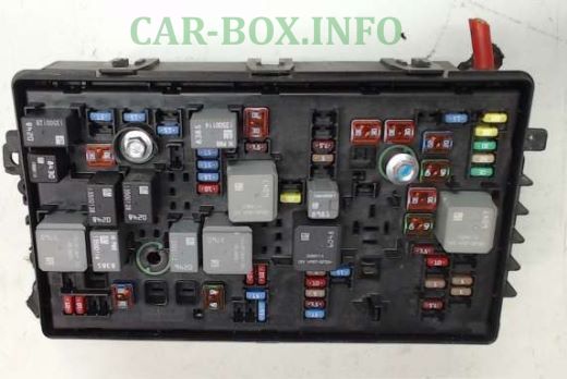
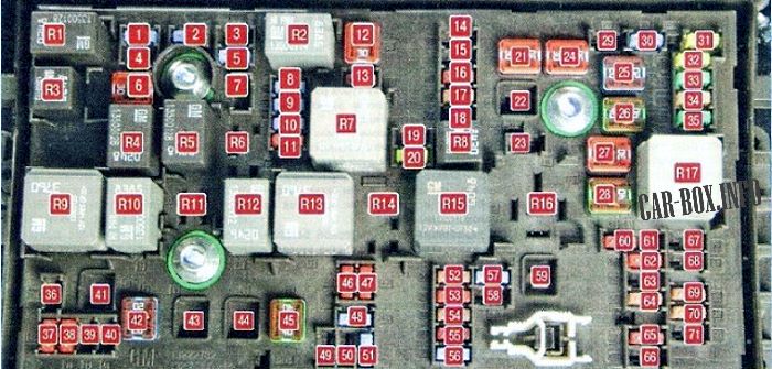
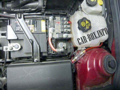
Main fuse box
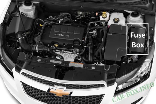
Located under the bonnet on the left side of the engine compartment, next to the headlight and battery. Closed with a plastic protective cover. 3 attachments from different sides.
Example photo.
| Diagram | |
|---|---|
|
|
| No. | Amps / Description |
| 1 | 15A Transmission control unit |
| 2 | 15A Engine control unit |
| 3 | Not used |
| 4 | 10A Canister air solenoid valve |
| 5 | 15A Ignition |
| 7 | Not used |
| 8 | 15A Fuel injection system |
| 9 | 15A Fuel injection system, ignition system |
| 10 | 15A Engine control unit |
| 11 | 10A oxygen concentration sensor |
| 13 | 7.5A Adsorber solenoid valve |
| 14 | Not used |
| 15 | 20A Rear window cleaner |
| 16 | 7.5A Ignition, interior air quality sensor (air conditioning system) |
| 17 | 5A Ignition, airbag |
| 18 | 10A Throttle position sensor |
| 19 | Not used |
| 20 | 20A Fuel pump |
| 22 23 29 |
Not used |
| 30 | 15A ABS |
| 31 | 20A Body control unit |
| 32 | 20A The same |
| 33 | 30A Heated front seats |
| 34 | 25A Sunroof |
| 35 | 30A Audio system |
| 36 | Not used |
| 37 | 10A Fuse for the right headlight high and low beam |
| 38 | 10A Left headlight high and low beam |
| 39 40 |
Not used |
| 46 | 10A Cooling fan |
| 47 | 10A oxygen concentration sensor |
| 48 | 15A Fog lights |
| 49 50 |
Not used |
| 51 | 15A Sound signal |
| 52 | 15A Dashboard |
| 53 | 10A Electric mirror |
| 54 | 5A Light switch, light control |
| 55 | 7.5A Folding mirrors |
| 56 | 15A Windshield washer |
| 57 | 15A Steering column lock |
| 58 | Not used |
| 60 | 7.5A Mirror heater |
| 61 | 7.5A Mirror heater |
| 62 | 10A Air condition |
| 63 | 7.5A Rear window sensor |
| 64 | 5A Air quality sensor |
| 65 | 7.5A Rear fog lights |
| 66 | 15A Rear window washer |
| 67 | 20A Fuel control unit |
| 68 | Not used |
| 69 | 5A Battery voltage sensor |
| 70 | 5A Rain sensor |
| 71 | Not used |
| Fusible links | |
| 6 | 30A Windshield wiper |
| 12 | 30A Pull starter relay |
| 21 | 30A Rear power windows |
| 22 | Not used |
| 24 | 30A Front power windows cruze |
| 25 | 20A Electronic Vacuum Pump |
| 26 | 40A ABS |
| 27 | 30A Electronic key control system |
| 28 | 40A Heated rear window |
| 41 | Not used |
| 42 | 20/30 / 40A Engine cooling fan |
| 43 44 |
Not used |
| 45 | 40A Engine cooling fan |
| 59 | 30A Diesel fuel heater |
| Relay | |
| R1 | A / C Compressor Drive Clutch |
| R2 | Starter traction relay |
| R3 | Engine cooling fan (K7) |
| R4 | Front wiper mode (speed) relay |
| R5 | Front wipers |
| R6 | Not used |
| R7 | Main relay of the engine management system |
| R8 | Fuel pump |
| R9 | Engine cooling fan (K2) |
| R10 | Engine cooling fan (KZ) |
| R11 | Not used |
| R12 | Engine cooling fan (KZ) |
| R13 | Engine cooling fan (K1) |
| R14 | Not used |
| R15 | Ignition |
| R16 | Preheating system (diesel) |
| R17 | Heated exterior mirrors |
Power fuses
High power fuse box Iocated on the battery.
| Diagram | |
|---|---|

|
|
| No, | Amps / Description |
| 1 | 100A Fuse Box - Instrument Panel |
| 2 | |
| 3 | 80A Electric Power Steering (EPS) (NJ1) |
| 4 | Not used |
| 5 | 250A Fuse Box - Additional Battery |
| 6 | 250 / 500А Starter motor |
Additional relay block
Depending on the configuration, there may be a separate unit with a relay under the hood.
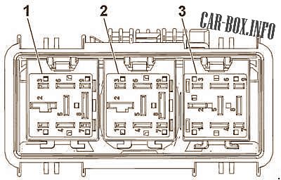
1 - Cooling fan medium speed relay;
2 - Cooling fan speed control relay;
3 - Cooling fan medium speed relay.

Where is the alarm fuse located in a 2012 Cruze Essence 1.6?