
Most electrical power circuits in the sedan, station wagon, and hatchback are protected by fuses. High-current loads are routed through relays. These protective components are housed in distribution boxes located within the engine compartment and the passenger compartment.
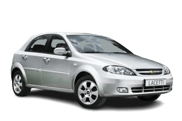
The diagram information applies to the first-generation Chevrolet Lacetti (J200), spanning model years 2004 through 2013.
The distribution box covers feature the fuse layout, amperage ratings, and schematic symbols for the protected circuits.
Engine Compartment
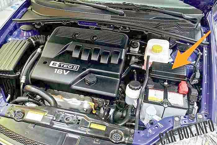
The fuse block is located on the left side of the engine compartment, between the coolant reservoir and the battery. Remove the protective cover to gain access.
| Diagram | |
|---|---|
|
|
| Relays | |
| No. | Description |
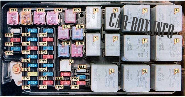
| 1 | Instrument and control illumination / 96190187 |
| 2 | Horn / 96190187 |
| 3 | Main relay / Ignition relay / 96190189 |
| 4 | Headlamp unit / 96190189 |
| 5 | Front fog lamps / 96190187 |
| 6 | A/C compressor clutch / 96190187 |
| 7 | Fuel pump relay / Fuel pump, ignition coils / 96190189 |
| 8 | Power windows / 96190189 |
| 9 | Engine cooling fan (low speed) / 96190189 |
| 10 | Rear window defogger / 96190189 |
| 11 | Engine cooling fan (high speed) / 96190189 |
| Fuses and Protected Circuits | ||
| No. | Amperage (A) | Description |
| PULLER | - | Fuse puller tool |
| Ef1 | 30 | Hazard warning flashers, anti-theft control module, diagnostic link connector (DLC), rear fog lamps, clock, A/C system, A/C switch, audio system, immobilizer, transmission control module (TCM) |
| Ef2 | 60 | ABS control module, ABS hydraulic unit |
| Ef3 | 30 | HVAC blower motor |
| Ef4 | 30 | Power windows, power mirrors, starter motor |
| Ef5 | 30 | Fuel pump relay, engine control module (ECM), exhaust gas recirculation (EGR) valve, ignition system, fuel pump, evaporative emissions (EVAP) purge valve, engine cooling fan |
| Ef6 | 20 | Engine cooling fan (low speed) |
| Ef7 | 30 | Rear window defogger |
| Ef8 | 30 | Engine cooling fan (high speed) |
| Ef9 | 20 | Power windows (passenger and rear doors) |
| Ef10 | 15 | Fuel pump relay, ECM, EGR valve, ignition system |
| Ef11 | 10 | Main relay power circuit |
| Ef12 | 25 | Headlamps, instrument and control illumination |
| Ef13 | 15 | Brake lamps |
| Ef14 | 20 | Power window (driver's door) |
| Ef15 | 15 | High beam headlamps |
| Ef16 | 15 | Horn |
| Ef17 | 10 | A/C compressor |
| Ef18 | 15 | Fuel pump power circuit |
| Ef19 | 15 | Instrument cluster, horn switch, power folding mirrors, map lamps, interior dome lamp, trunk/cargo lamp, tailgate ajar switch |
| Ef20 | 10 | Low beam (left headlamp) |
| Ef21 | 15 | EVAP canister purge valve, heated oxygen sensor (HO2S), engine cooling fan |
| Ef22 | 15 | Fuel injectors, EGR system |
| Ef23 | 10 | License plate lamps, hazard warning flashers, left tail lamp, left headlamp unit |
| Ef24 | 15 | Front fog lamps |
| Ef25 | 10 | Power adjustable and heated exterior mirrors |
| Ef26 | 15 | Central locking system |
| Ef27 | 10 | Low beam (right headlamp) |
| Ef28 | 10 | License plate lamps, hazard warning flashers, right tail lamp, right headlamp unit |
| Ef29 | 10 | Spare |
| Ef30 | 15 | Spare |
| Ef31 | 10 | Spare |
Passenger Compartment
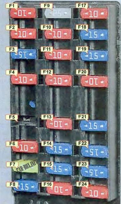
Interior Fuse Panel
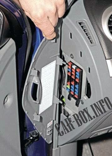
Located on the left side of the dashboard. To access it, open the driver’s door and remove the fuse panel cover.
| Diagram | |
|---|---|
|
|
| No. | Amperage (A) / Description |
| F1 | 10A AIRBAG - Supplemental Restraint System (SRS) control module |
| F2 | 10A ECM - Engine control module (ECM), transmission control module (TCM)*, alternator, vehicle speed sensor (VSS) |
| F3 | 15A TURN SIGNAL - Hazard warning switch, turn signals |
| F4 | 10A CLUSTER - Instrument cluster, automatic low beam headlamp module*, warning chime, brake lamp switch, variable effort steering (VES) control module*, A/C switch* |
| F5 | Spare |
| F6 | 10A ENG FUSE - A/C compressor relay, rear window defogger relay, power window relay, headlamp relay |
| F7 | 20A HVAC - HVAC blower motor relay, A/C switch, climate control system* |
| F8 | 15A SUNROOF - Power mirror switch, power folding mirrors*, power sunroof* |
| F9 | 25A WIPER - Windshield wiper motor, wiper control switch |
| F10 | 10A HANDS FREE - Hands-free audio system |
| F11 | 10A ABS - ABS control module, ABS hydraulic unit |
| F12 | 10A IMMOBILIZER - Immobilizer, anti-theft control module, rain sensor |
| F13 | 10A - Transmission control module (TCM)* |
| F14 | 15A HAZARD - Hazard warning switch |
| F15 | 15A ANTI-THEFT - Anti-theft control module |
| F16 | 10A DIAGNOSIS - Diagnostic link connector (DLC) |
| F17 | 10A AUDIO / CLOCK - Audio system, clock |
| F18 | 15A EXTRA JACK - Auxiliary power outlet |
| F19 | 15A CIGAR LIGHTER - Cigarette lighter |
| F20 | 10A BACK-UP - Reverse lamp switch, automatic transmission gear selector* |
| F21 | 15A REAR FOG - Rear fog lamp relay, instrument and control illumination relay, parking lamps |
| F22 | 15A ATC / CLOCK - Clock, climate control system*, A/C switch* |
| F23 | 15A AUDIO - Audio system |
| F24 | 10A IMMOBILIZER - Immobilizer |
Auxiliary Relay Modules

To access these modules, open the coin box and remove the two retaining screws using a screwdriver.
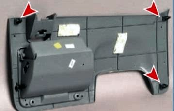
Next, carefully disengage the three retaining clips to detach the lower instrument panel trim.
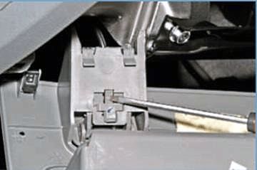
Then, press the release latch to disconnect the hood release handle and completely remove the lower trim panel. The relays are mounted on a bracket attached to the dashboard frame.

The relay modules are now accessible.
Under-Dash Relay Diagram
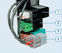
Component identification: 1 - Battery saver control module; 2 - Turn signal flasher; 3 - Rear fog lamp relay; 4 - Starter interrupt relay (for vehicles with automatic transmission). Depending on the vehicle trim level, a BLOWER RELAY (HVAC blower motor relay) and a DRL RELAY (Daytime Running Lamps relay) may also be installed in this location.
