Table of Contents
The updated Chevrolet Trax appeared on the market in 2013 as a mini crossover. Released in 2014, 2015, 2016, 2017 and 2018. Also known as the Chevrolet Tracker. We will look at all the fuse boxes and relays of the model with photos and locations of distribution boxes.

In the engine compartment
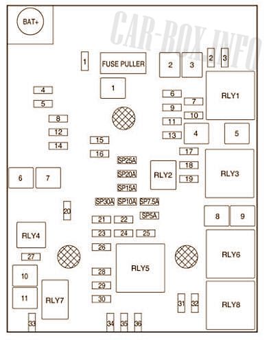
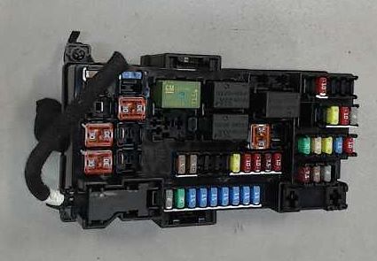
Main fuse box
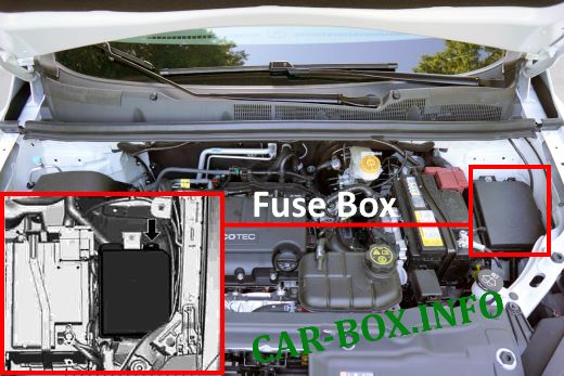
Located on the left side, near the battery.
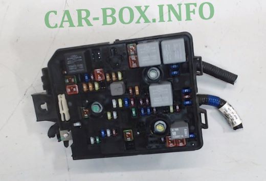
General view.
| Diagram | |
|---|---|
|
|
| No. | Mini |
| 1 | Roof ventilation hatch |
| 2 | OSRVM SW |
| 3 | Valve for supplying fuel vapor to the adsorber |
| 4 | Not used |
| 5 | Electronic brake control valve |
| 6 | "INTELLIGENT" BRAKE SYSTEM |
| 7 | Not used |
| 8 | TCM B + |
| 9 | Not used |
| 10 | Headlamp tilt adjustment, left / right |
| 11 | Rear window wiper |
| 12 | Rear window blowing |
| 13 | Not used |
| 14 | Heating OSRVM |
| 15 | FSCM B + |
| 16 | Seat heating module |
| 17 | TCM R / C |
| 18 | ECM R / C |
| 19 | Fuel pump |
| 20 | Not used |
| 21 | Petrol: FAN RELAY (AUX BEC), Diesel: Fan 3 relay 85 |
| 22 | Not used |
| 23 | Gasoline: Ignition / Injector Coil Diesel: ECM PT IGN-2 |
| 24 | Washer pump |
| 25 | Not used |
| 26 | Gasoline: Carbon filter purge solenoid valve / Water solenoid valve / Turbocharger pressure solenoid valve / Wastegate solenoid valve |
| Turbocharger / Inlet / Outlet O2 Sensor / IMTV Solenoid Valve Diesel: Swirl Solenoid, Piston Jet Cooling Solenoid, Engine Oil Control Solenoid | |
| 27 | Not used |
| 28 | Gasoline: Not used Diesel: ECM PT IGN-3 |
| 29 | Petrol: ECM PT IGN-1 / IGN-2 Diesel: ECM PT IGN-1 |
| 30 | Gasoline: MAF sensor Diesel: O2 sensor, exhaust gas particulate sensor |
| 31 | Main beam left |
| 32 | High beam right |
| 33 | ECM B + |
| 34 | Sound signal |
| 35 | Air conditioner coupling |
| 36 | Front fog lamp |
| No. | Midi |
| 1 | Electronic brake control pump |
| 2 | Front glass cleaner |
| 3 | Blower fan |
| 4 | IEC R / C |
| 5 | Not used |
| 6 | Gasoline: Not used Diesel: Fuel heater |
| 7 | Not used |
| 8 | Low / medium speed cooling fan |
| 9 | high speed cooling fan |
| 10 | Gasoline: EVP Diesel: Glow plug |
| 10 | Starter solenoid valve |
| No. | Relays |
| RLY1 | Crankshaft start |
| RLY2 | Fuel pump |
| RLY3 | Cooling fan medium speed |
| RLY4 | Reserve |
| RLY5 | Relay PT |
| RLY6 | High speed cooling fan |
| RLY7 | Starter |
| RLY8 | Low speed cooling fan |
Additional fuse box

Location
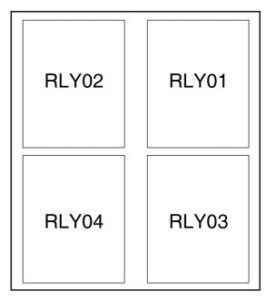
- 01 Relay for electric vacuum pump
- 02 Cooling fan drive relay 1
- 03 Cooling fan drive relay 2
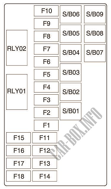
In the passenger compartment
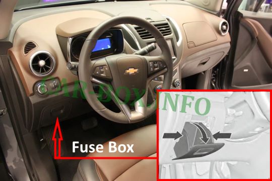
The internal fuse box is located under the dash on the driver's side, behind the glove compartment. Remove the storage compartment to access the fuses. To remove the storage compartment, open it and simply pull it towards you.
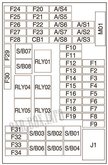
General view.
| Diagram | |
|---|---|
|
|
| No. | Description |
| RLY01 | RELAY BATTERY / RAP |
| RLY 02 | L / Gate relay |
| RLY 03 | Spare relay |
| RLY 04 | Blower relay |
| RLY 05 | Communication mode relay |
| F1 | Body control unit 1 |
| F2 | Body control unit 2 |
| F3 | Body control module 3 |
| F4 | Body control unit 4 |
| F5 | Body control unit 5 |
| F6 | Body control unit 6 |
| F7 | BCM 7 |
| F8 | Body control unit 8 |
| F9 | DLIS |
| F10 | SDM B + |
| F11 | DLC |
| F12 | HVAC SRD |
| F13 | L / Gate relay |
| F14 | UPA SRD |
| F15 | Not used |
| F16 | Reserve |
| F17 | PWR WNDWSW DR |
| F18 | Rain sensor |
| F19 | BCM RVC |
| F20 | SWC BKLT |
| F21 | AC APO |
| F22 | Cigarette lighter / DC APO |
| F23 | Reserve |
| F24 | Reserve |
| F25 | Reserve |
| F26 | AOS display |
| F27 | IPC / CMPS SRD |
| F28 | Switch. headlights / DC converter / Clutch switch |
| F29 | Reserve |
| F30 | Reserve |
| F31 | IPC B + |
| F32 | RDO / Alarm / AUX jack |
| F33 | Not used |
| F34 | Onstar UHP / DAB |
| SBSB01 | PTC 1 |
| SB02 | PTC 2 |
| SB03 | PWR WNDW MTR BEFORE |
| SB04 | Rear window regulator sensor |
| SB05 | Communication mode relay |
| SB06 | Reserve |
| SB07 | PWR WNDW BEFORE |
| SB08 | Rear electric glass lift |
In the luggage compartment
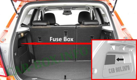
Fuse box located on the left side of the vehicle..
| Diagram | |
|---|---|
|
|
| No. | Description |
| RLY1 | Run / Start |
| RLY2 | Running |
| F1 | PWR LUM SW DR |
| F2 | PWR LUM SW PASS |
| F3 | Amplifier |
| F4 | Trailer socket |
| F5 | AWD SRD |
| F6 | AOS MDL |
| F7 | Reserve |
| F8 | Art. signal. trailer |
| F9 | Reserve |
| F10 | Reserve / SBZA B + |
| F11 | TRLR MDL |
| F12 | NAV. Dock |
| F13 | Reserve |
| F14 | Trailer socket |
| F15 | EVP SW |
| F16 | Fuel heater |
| F17 | ISRVM / RVC |
| F18 | Reserve |
| Relay in extended interval | |
| SB01 | Power seat / SRD memory |
| SB02 | Reserve |
| SB03 | TRLR MDL |
| SB04 | ACDCINV |
| SB05 | Battery + |
| SB06 | Reserve |
| SB07 | Reserve |
| SB08 | Reserve |
| SB09 | Reserve |
View and print PDF:
