
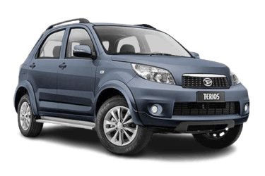
The Daihatsu Terios is a 5-door compact SUV initially introduced at the 1997 Geneva Motor Show. This article provides a comprehensive overview of the fuse box diagrams for the second-generation Daihatsu Terios (J200 chassis), covering model years 2006 through 2018.
Fuse F13 in the passenger compartment fuse box protects the cigarette lighter electrical circuit.
Passenger Compartment
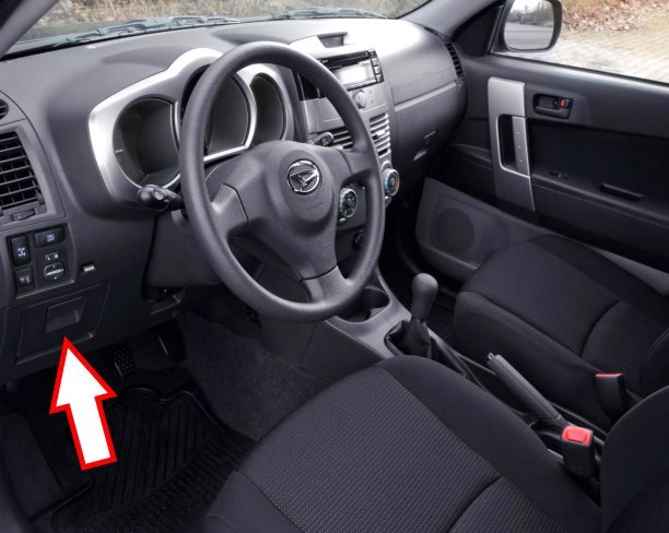
The interior fuse box is located on the driver’s side, behind the instrument panel trim.

An example of the installed passenger compartment fuse box.
| Diagram | ||
|---|---|---|

|
||
| No. | Circuit Description | Rating (A) |
| F1 | Starter motor | 7.5 |
| F2 | Central locking system | 15 |
| F3 | Turn signals and hazard warning lights | 10 |
| F4 | - | 25 |
| F5 | Power windows | 30 |
| F6 | Auxiliary power outlet | 15 |
| F7 | Engine control module (ECM) | 10 |
| F8 | - | 7.5 |
| F9 | Rear window defogger | 15 |
| F10 | - | 7.5 |
| F11 | - | 7.5 |
| F12 | - | 7.5 |
| F13 | Cigarette lighter, auxiliary power outlet | 15 |
| 1 | Starter relay | |
| 2 | Turn signal flasher relay | |
| 3 | Ignition main relay | |
| 4 | Engine control relay | |
| 5 | Horn relay | |
| 6 | Fuel pump relay | |
Engine Compartment
There are two fuse blocks located in the engine compartment.
Engine Compartment Fuse Box 1

Located on the right side of the engine compartment, beneath the protective cover.

General view of the fuse box.
| Diagram | ||
|---|---|---|

|
||
| No. | Circuit Description | Rating (A) |
| F1 | ABS/ESP module | 30 |
| F2 | - | 15 |
| F3 | Interior lighting | 7.5 |
| F4 | Front and rear position lights | 10 |
| F5 | ABS/ESP module | 30 |
| F6 | Transmission control module (TCM) | 10 |
| F7 | Brake lights | 15 |
| F8 | Air conditioning (A/C) system | 10 |
| F9 | Horn | 10 |
| F10 | - | 15 |
| F11 | Fog lights | 7.5 |
| F12 | Fog lights | 7.5 |
| F13 | Headlight (RH) | 10 |
| F14 | Headlight (LH) | 10 |
| F15 | Headlight (RH) | 10 |
| F16 | Headlight (LH) | 10 |
| F17 | Heated seats | 10 |
| F18 | - | 50 |
| F19 | - | - |
| F20 | Ignition main circuit | 50 |
| F21 | ABS/ESP module | 40 / 50 |
| F22 | Ignition main circuit | 30 |
| F23 | Radiator cooling fan motor | 30 |
| F24 | - | - |
| F25 | HVAC blower motor | 40 |
| 1 | - | |
| 2 | Radiator cooling fan relay | |
| 3 | Headlight relay | |
| 4 | Air conditioning (A/C) relay | |
| 5 | Fog light relay | |
Engine Compartment Fuse Box 2
Located on the left side of the engine compartment.

Circuit assignment:
- F1 - ABS/ESP module (7.5 A)
- 1 - ABS relay
- 2 - ABS relay
- 3 - ABS pump motor relay
