Bravo and Brava are two small cars with three- and five-door hatchback bodies, produced from 1995 to 2003 by the Italian company Fiat. For the first time, the concern decided to differently name two models, created on the same base, but differing in size, appearance and market orientation. In this article, we will take a detailed look at the fuse box diagrams for the Fiat Bravo and Brava (1st generation; code body 182) 1995, 1996, 1997, 1998, 1999, 2000, 2001, 2002, 2003 years of manufacture.
Here you will find the locations and photos of distribution boxes. The fuses responsible for the “Cigarette lighter” and “Fuel Pump” are highlighted in bold.
In the passenger compartment
There are two distribution boxes here that are responsible for protecting the electrical circuits.
Main fuse box
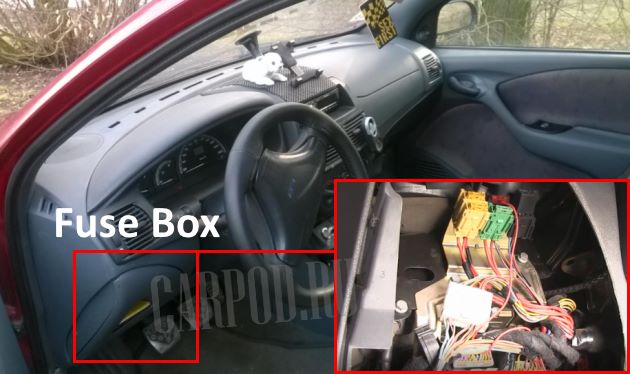
It is located near the steering wheel, at the bottom of the dashboard behind the protective cover. To access the distribution box, remove the cover by unscrewing the two mounting screws.
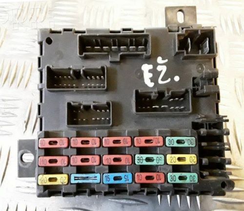
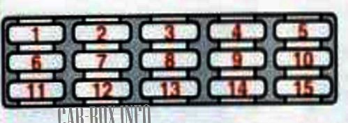
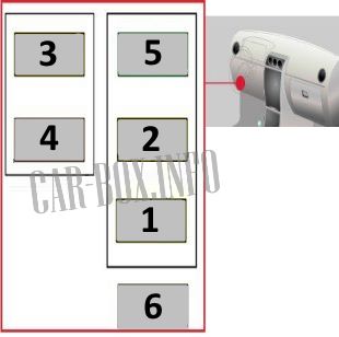
PGeneral view of the Fiat Bravo / Brava interior fuse box.
| Diagram | ||
|---|---|---|
|
||
| No. | Description | A |
| 1 | Rear window heater, door mirror heater | 20 |
| 2 | Emergency alarm | 10 |
| 3 | Reverse lights, brake lights, clock, turn indicators, instrument cluster, power door mirrors, ABS / SRS system, power window lifters | 15 |
| 4 | Interior light bulbs, tailgate light bulb, clock, duffel box light bulb, anti-theft indicator light | 15 |
| 5 | Horn (beep) | 20 |
| 6 | Windshield wipers, rear window wiper, windshield washers, headlight washers | 20 |
| 7 | Heater fan, cigarette lighter fuse Fiat Bravo / Brava | 20 |
| 8 | Right headlight - dipped beam, headlight corrector | 10 |
| 9 | Front position lamp - left, rear position lamp - left, heater control panel, heater control panel illumination lamps, license plate illumination lamp | 10 |
| 10 | Front position lamp - right, rear position lamp - left, license plate illumination lamp, radio receiver illumination lamp, instrument cluster illumination lamps, cigarette lighter illumination lamp, switch illumination lamps | 10 |
| 11 | Reserve | 30 |
| 12 | Dipped beam - left headlight | 10 |
| 13 | Rear fog lights | 10 |
| 14 | High beam - left headlamp, high beam indicator light | 10 |
| 15 | High Beam - Right Headlight | 10 |
Auxilary fuse panel
Located near the main unit.
|
||
| No. | Purpose of the fuses | A |
| 1 | Sunroof, heated seats | 20 |
| 2 | Fog lights | 20 |
| 3 | central locking system | 20 |
| 4 | Safety Airbag | 5 |
| 5 | Power windows | 30 |
| 6 | ABS/ESP | 7.5 |
In the engine compartment
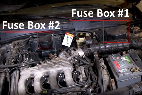
Unit #1 is located in the left rear of the underhood. Unit No. 2 is located in the rear center.
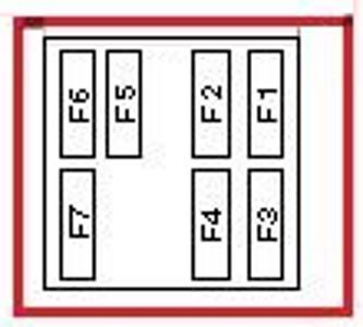
Fuse box #1
Assigment of fuses in the engine compartment block #1
| Diagram | ||
|---|---|---|
|
||
| No. | Description | A |
| F1 | fuel injection system | 30 |
| F2 | Ignition lock | 40 |
| F3 | Reserve | 60 |
| F4 | Fuse box | 80 |
| F5 | Cooling fan motor | 40 |
| F6 | Air conditioner | 50 |
| F7 | ABS | 60 |
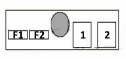
Fuse box #2
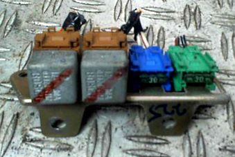
General view.
| Diagram | ||
|---|---|---|
|
||
| No. | Purpose | A |
| F1 | Injection system (1.4) | 10 |
| F2 | Fiat Bravo / Brava fuel pump fuse (1.4) | 10 |
| 1 | ECM relay (1.4) | |
| 2 | Fuel pump relay (1.6) | |
