Fiat Ducato of the second generation was launched in 1993. In 2002, the model was restyled. The cars were produced in Italy until 2006. Cars for the Russian market were produced in Elabuga from 2006 to 2011. In this article, we will take a detailed look at the fuse box diagrams for the Fiat Ducato (2nd Gen; body 244 and 230) 1993, 1994, 1995, 1996, 1997, 1998, 1998, 1999, 2000, 2001, 2002, 2003, 2004, 2005, 2005, 2006, 2007, 2007, 2008, 2009, 2010, 2011 years of manufacture.
Here you will find the locations and photos of distribution boxes. The fuses responsible for the “Cigarette lighter” and “Fuel Pump” are highlighted in bold.
In the engine compartment
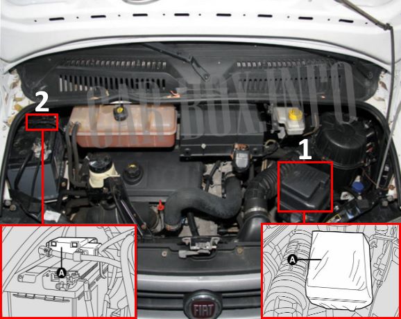
Location of components:
1 - fuse box (to gain access, remove the protective cover, loosen the fixing screw, then release the catch and remove the protective cover).
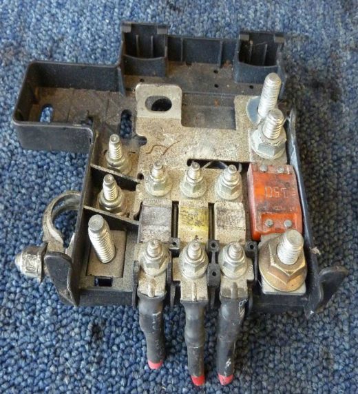
2 - fusible links on the battery.
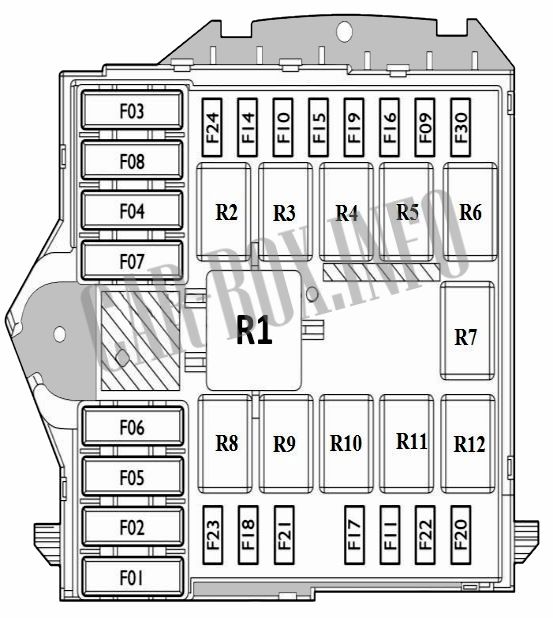
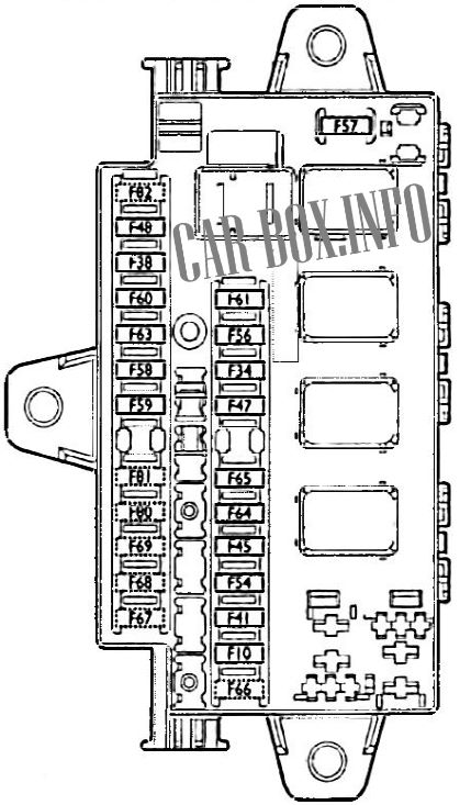
Fuse box
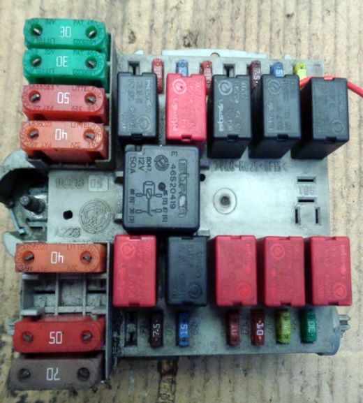
General view.
| Diagram | ||
|---|---|---|
|
||
| Purpose of fuses | No. | A |
| Radiator fan speed reduction resistor (2.0L with climate control) | F06 | 40 |
| Engine control unit (2.0l with climate control system) | 40 | |
| Cooling fan (2.0L with climate control system) | 40 | |
| Engine control unit (2.0l with climate control system) | 40 | |
| Cooling fan (2.0L with climate control system) | F07 | 40 |
| Engine control unit (2.0l with climate control system) | 40 | |
| Primary devices of the E.I. system. | F17 | 5 |
| Primary devices of the E.I. system. | F22 | 20 |
| Secondary devices of the E.I. system. | F11 | 10 |
| Horn (beep) | F10 | 15 |
| Steering column lock control | 15 | |
| Front fog lights | F09 | 15 |
| Wiper motor | F08 | 30 |
| Cooling fan, second speed | F07 | 40/60 |
| Fan motor control unit, second speed | 40/60 | |
| Radiator fan remote switch coil, second speed (climate control) | 40/60 | |
| Cooling fan, first speed | F06 | 40 |
| Fan motor control unit, first speed | 40 | |
| Cabin fan (together with climate control) | F05 | 30 |
| ABS control unit | F04 | 50 |
| Ignition lock | F03 | 30 |
| glow plugs | F02 | 50 |
| Right headlight (dipped beam) | F14 | 10 |
| Left headlight (dipped beam) | F15 | 10 |
| EI system | F16 | 7.5 |
| FIAT CODE engine start blocking system | 7.5 | |
| Automatic transmission control unit | F24 | 15 |
| Engine immobilizer system "FIAT CODE* | F18 | 7.5 |
| Compressor | F19 | 7.5 |
| The engine control unit | F18 | 7.5 |
| RTS | F20 | 30 |
| The engine control unit | F11 | 10 |
| fuel pump fuse | F21 | 15 |
| The engine control unit | F17 | 5 |
| Automatic transmission control unit | F23 | 10 |
| Headlights (high beam) | F30 | 15 |
| Windshield washer pump | F08 | 30 |
| Purpose of relay modules | ||
| Cooling fan 2 | R1 | |
| Dpped beam | R2 | |
| washer pump | R3 | |
| Wiper | ||
| Horn | R4 | |
| high beam | R5 | |
| Front fog lights | R6 | |
| Compressor clutch | R7 | |
| Cooling fan 1 | R8 | |
| Engine management | R9 | |
| Engine management | R10 | |
| Compressor clutch | ||
| Automatic transmission | R11 | |
| Engine management | R12 | |
Fusible links
Located on the battery.
| Diagram | ||
|---|---|---|
|
||
| No. | Description | A |
| F73 | Integrated socket | 70 |
| F72 | Alternator | 125 |
| Alternator (engines 2.0 - 2.0 JTD with preheating system) | 70 | |
| F 72 F 70 |
Alternator (2.8 JTD engines with preheating system - 2.0 JTD engines with climate control system) | 100 |
| 150 | ||
| F 71 | Protection of fuse boxes in the cabin and under the hood | 80 |
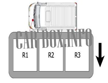
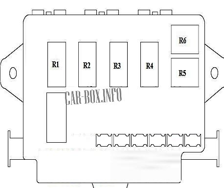
Additional relay box
Location and description.
|
|
| No. | Description |
| R1 | Fan |
| R2 | Fan, low speed |
| R3 | Fan, high speed |
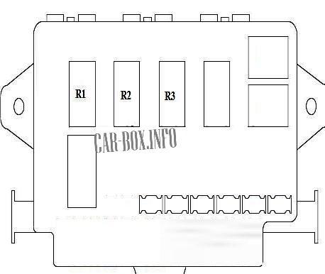
Separate relays
Individual relay modules

|
|
| R1 | Inlet manifold heater |
| R2 | Heater control |
| R3 | Cooling Fan |
In the passenger compartment
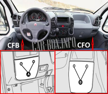
Component Location:
- CFB unit - located on the left side of the dashboard on the driver's side (or passenger side on right-hand drive models). To access the fuses, remove the two mounting screws (A).
- CFO unit - located on the right side of the instrument panel on the passenger side (or driver's side on right-hand drive models). Remove the two screws (B) to gain access.
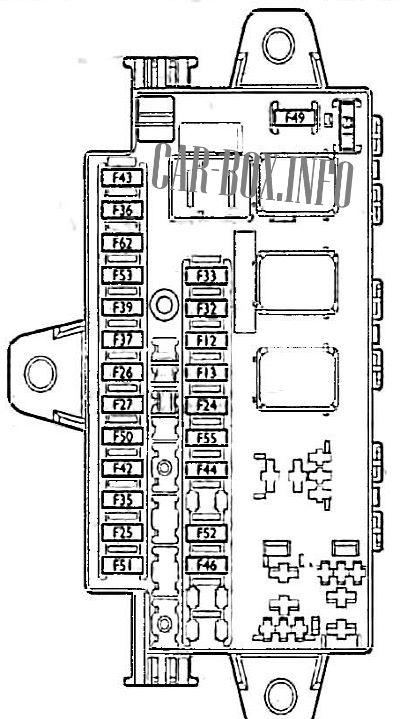
CFO block
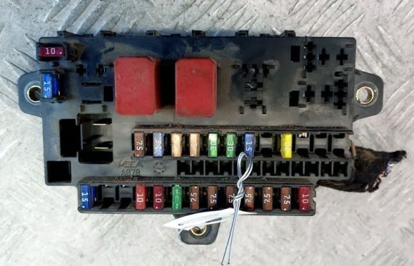
General view of the Fiat Ducato interior (CFO) fuse box.
CFB block
Located on the left.
| Diagram | ||
|---|---|---|
|
||
| Purpose | No. | A |
| Windshield washer pump | F 43 | 15 |
| Cigarette lighter fuse Fiat Ducato 2 | F 44 | 15 |
| Cabin heater fan | F 5 | 30 |
| direction indicators | F 53 | 10 |
| Emergency alarm | F 53 | 10 |
| instrument cluster | F 53 | 10 |
| Cabin lighting | F 39 | 10 |
| Diagnostic Connector (EOBD) | F 39 | 10 |
| Rear fog lights | F 33 | 7.5 |
| Radio | F 32 | 15 |
| Front 12V electrical outlet | F 52 | 20 |
| headlight washer pump | F 49 | 15 |
| Front right position lamp | F 12 | 5 |
| Rear right position lamp | F 12 | 5 |
| Front left position lamp | F 13 | 5 |
| Rear left position lamp | F 13 | 5 |
| License plate illumination lamps | F 24 | 5 |
| Indicator lamp for parking lights | F 24 | 5 |
| Signal lamps | F 24 | 5 |
| PCA (Modifications Ambulance J-Minibus) | F 51 | 10 |
| Radio | F 25 | 7.5 |
| HELP | F 35 | 7.5 |
| Power window control | F 35 | 7.5 |
| ABS control unit | F 42 | 7.5 |
| Safety Airbag control unit | F50 | 7.5 |
| Mirror drive | F 27 | 7.5 |
| Cruise control | F 27 | 7.5 |
| Telephone | F 27 | 7.5 |
| Tachograph | F 27 | 7.5 |
| Remote control | F 27 | 7.5 |
| Security alarm | F 27 | 7.5 |
| Stop lights | F 26 | 7.5 |
| instrument cluster | F37 | 10 |
| RSS | F37 | 10 |
| Ignition lock | F 31 | 10 |
| Cabin fan (together with Webasto system) | F 55 | 30 |
| Webasto system control unit | F 55 | 30 |
| Cabin fan (together with climate control) | F 55 | 30 |
| Relay modules | ||
|
||
| headlight washer | R1 | |
| optional equipment | R2 | |
| R3 | ||
Auxilary fuse panel
Installed only on 1994-2002 Fiat Ducato in the 230 body
| Diagram | ||
|---|---|---|

|
||
| No. | Purpose | A |
| 1 | Dashboard | 10 |
| Electronic anti-theft device | ||
| Heater panel illumination | ||
| headlight adjustment | ||
| instrument lighting | ||
| Clock illumination | ||
| direction indicators | ||
| Tachograph backlight | ||
| Diesel pollution sensor | ||
| Water in diesel warning light | ||
| 2 | Headlight washers | 7.5 |
| Tachograph | ||
| ABS warning lamp | ||
| 3 | Wipers | 15 |
| Windshield washer | ||
| Clock | ||
| Heated seats | ||
| 4 | Headlight washers | 7.5 |
| 5 | Light control switch | 10 |
| ABS | ||
| Left side light | ||
| Right rear light | ||
| 6 | Right side light | 7.5 |
| Left rear light | ||
| instrument lighting | ||
| License plate illumination lamp | ||
| Light on | ||
| 7 | Left dipped beam | 10 |
| 8 | Right dipped beam | 10 |
| 9 | high beam | 10 |
| 10 | Right high beam | 10 |
| 11 | Cigarette lighter fuse Fiat Ducato 230 | 15 |
| Interior lighting | ||
| Clock | ||
| Radio | ||
| 12 | Power windows | 20 |
| Horn (beep) | ||
| Stop lights (minibus) | ||
| 13 | heater | 20 |
| Additional heater | ||
| 14 | Interior lighting | 15 |
| Rear fog lights | ||
| 15 | Heated rear windshield | 20 |
| heated mirror | ||
| 16 | glow plug system | 5 |
| 17 | Tachograph | 10 |
| Luggage compartment lighting | ||
| Cigarette lighter illumination | ||
| Stop lights | ||
| Hazard warning lights | ||
| Emergency light switch signaling | ||
| Clock (minibus) | ||
| 18 | Heated fuel filter, diesel | 30 |
