FIAT Ducato of the third generation was produced at the SEVEL plant located in Val di Sangro (Abruzzo region, Italy) since 2006 without significant changes. In Russia, it was officially sold since 2012. In this article, we will take a detailed look at the fuse box diagrams for the Fiat Ducato (3rd Gen; factory index 250) 2006, 2007, 2008, 2009, 2009, 2010, 2011, 2012, 2013, 2014 years of manufacture.
Here you will find the locations and photos of distribution boxes. The fuses responsible for the “Cigarette lighter” and “Fuel Pump” are highlighted in bold.
In the engine compartment
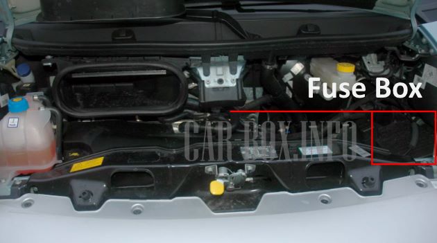
It is located on the right side, behind the protective cover.
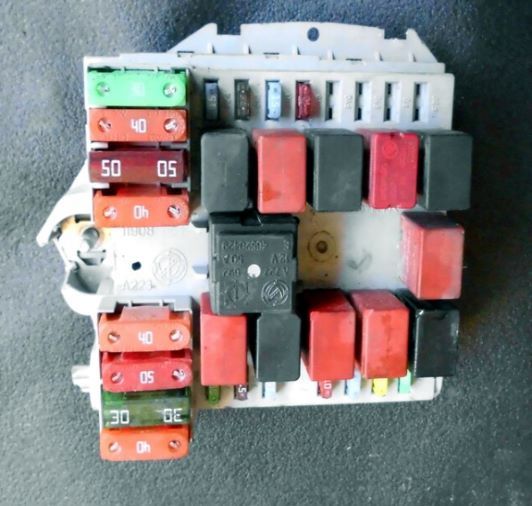
General view.
| Diagram | ||
|---|---|---|

|
||
| No. | Description | A |
| 1 | Vacuum brake pump | 40 |
| 2 | Glow Plugs (Diesel) | 50 |
| 3 | Ignition lock | 30 |
| 4 | Cooling Fan | 20 |
| 5 | 20 | |
| 6 | Cooling fan, high speed | 40 |
| 7 | Cooling fan, low speed | 40 |
| 8 | Climate control | 40 |
| 9 | Washer pump | 20 |
| 10 | Horn (beep) | 15 |
| 11 | Engine management | 15 |
| 14 | Right main beam | 7.5 |
| 15 | Left main beam | 7.5 |
| 16 | Engine management | 7.5 |
| 17 | 10 | |
| 18 | 7.5 | |
| 19 | Air conditioner | 7.5 |
| 20 | headlight washer pump | 30 |
| 21 | Fuel module (Fiat Ducato fuel pump fuse) | 15 |
| 23 | Brake system | 30 |
| 24 | Spare | - |
| 30 | Fog lights | 15 |
| Purpose of relay modules | ||
| R2 | high beam | |
| R3 | horn (beep) relay | |
| R5 | air conditioning compressor clutch | |
| R6 | fan 1 | |
| R7 | fan 2 | |
| R8 | Climate control | |
| R9 | Main relay | |
| R10 | fuel module (fuel pump relay Fiat Ducato 3) | |
| R14 | fog lights | |
| R17 | Windshield washer pump | |
| R19 | headlight washer pump | |
| R20 | Spare | |
In the passenger compartment
There are three distribution boxes here, which are responsible for protecting the vehicle's electrical circuits.
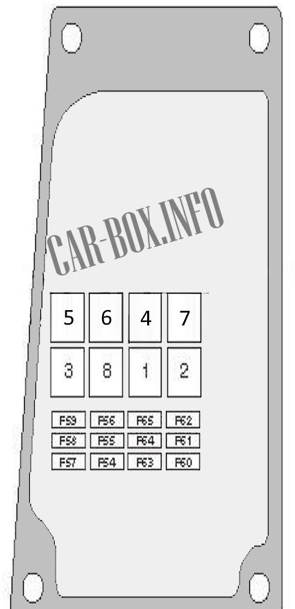
Main fuse box
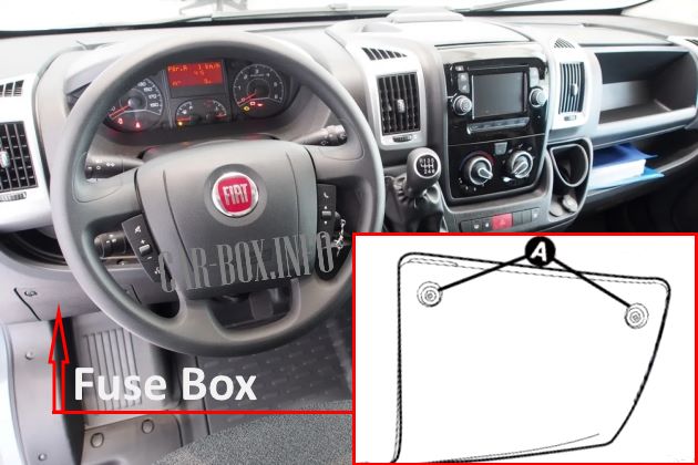
Located on the left side of the instrument panel. To access the distribution box, loosen the screws (A) and remove the protective cover.
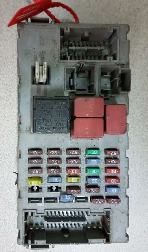
General view of the Fiat Ducato cabin fuse box.
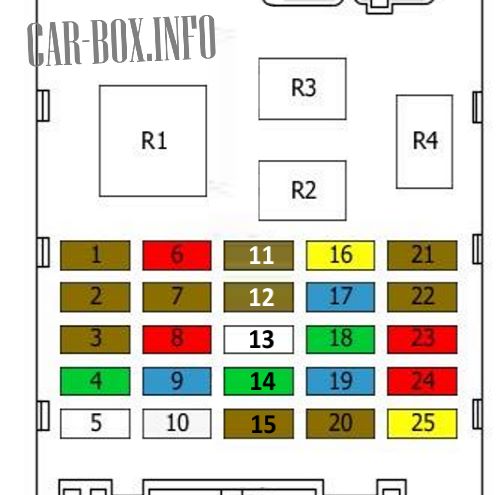
| Diagram | ||
|---|---|---|
|
||
| No. | Description | A |
| 1 | Left dipped beam, Headlight corrector | 7.5 |
| 2 | Brake pedal switch, Back-up lamp, Water sensor (diesel), Power steering control unit | 7.5 |
| 3 | Radio, Parking sensor, Rain sensor, Rearview camera, Driver's side window elevator | 7.5 |
| 4 | Right Power Window Power Supply | 30 |
| 5 | Not used | - |
| 6 | Right dipped beam | 10 |
| 7 | Steering angle sensor, Stop lamp switch, Speed sensor, ABS/ESP control unit | 7.5 |
| 8 | Stoplight switch | 10 |
| 9 | Rear 12V power outlet | 15 |
| 10 | Not used | 25 |
| 11 | Air conditioning, tachograph, cruise control, body control unit | 7.5 |
| 12 | Airbag | 7.5 |
| 13 | Not used | - |
| 14 | Left power window | 30 |
| 15 | Driver and front passenger door control unit | 7.5 |
| 16 | Cigarette lighter fuse Fiat Ducato 250, 12 V power outlet | 20 |
| 17 | Heated rear window, Electrically heated door mirrors | 15 |
| 18 | Wipers, Rear window washer | 30 |
| 19 | Heated rear window, Electrically heated door mirrors | 15 |
| 20 | Key discharge relay | 7.5 |
| 21 | Body Control Module, Relay in Engine Compartment Fuse/Relay Box | 7.5 |
| 22 | Instrument panel, Rear fog lamps | 7.5 |
| 23 | Body control unit | 10 |
| 24 | Alarm, air conditioning, tachograph, diagnostic socket | 10 |
| 25 | Door lock | 20 |
| R1 | Key extraction relay | |
| R2 | rear window heating | |
| R3 | ignition key release relay | |
| R4 | high beam | |
Additional fuse panel
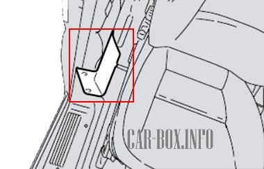
The auxiliary unit (its availability depends on the equipment) is located on the center pillar on the passenger side.
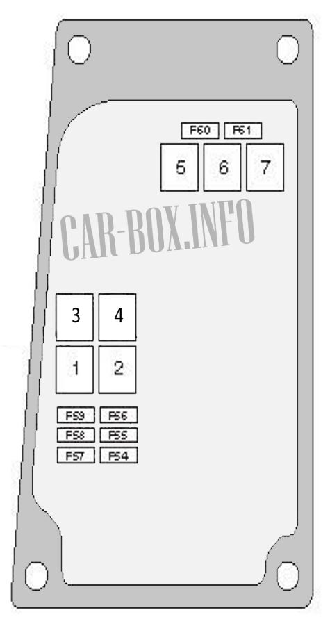
| Diagram | ||
|---|---|---|
| No. | Description | A |
| Type 1 | ||
|
||
| F54 | Air conditioning / heating system | 10 |
| F55 | Heated seats | 15 |
| F56 | Reserve | 15 |
| F57 | Air conditioning / heating system | 10 |
| F58 | dipped headlights | 10 |
| F59 | Self-levelling suspension | 7.5 |
| F60 | Air conditioning / heating system | 10 |
| F61 | 30 | |
| 2 | cigarette lighter relay | |
| 3 | Parking light relay | |
| Type 2 | ||
|
||
| F54 | Air conditioning / heating system | 10 |
| F55 | Heated seats | 15 |
| F56 | Rear passenger 12V power outlet | 15 |
| F57 | Air conditioning / heating system | 10 |
| F58 | Dipped beam headlights relay | 10 |
| F59 | Self-levelling suspension | 7.5 |
| F60 | Reserve | - |
| F61 | Reserve | - |
| F62 | Reserve | - |
| F63 | Air conditioning / heating system | 10 |
| F64 | Reserve | - |
| F65 | Air conditioning / heating system | 30 |
| 5 | Parking light relay | |
| 6 | Additional heater relay | |
| 8 | cigarette lighter relay | |
Power fuse panel #1
Under the driver's seat is a panel of heavy-duty fuses.
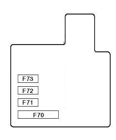
- F70 - Underhood fuse box circuit protection 150A;
- F71 - Special equipment for vehicles 50A;
- F72/F73 - Cabin fuse box circuit protection 50A
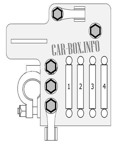
Power fuse panel #2
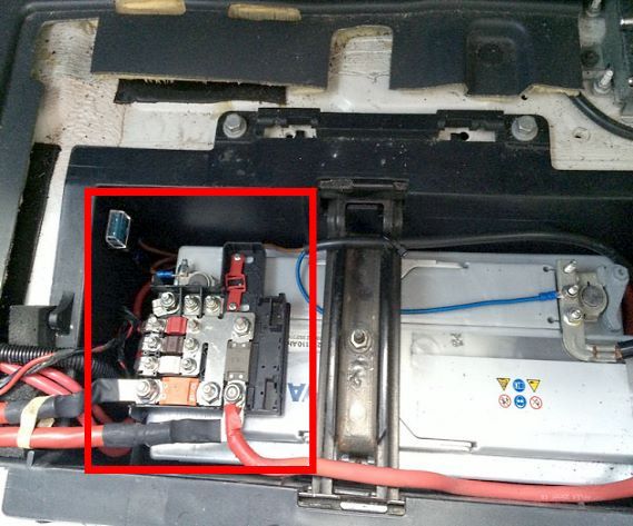
The battery is located in the driver's feet behind the floor covering. Powerful fusible links are installed on its positive terminal.
| Diagram | ||
|---|---|---|
|
||
| No. | Description | A |
| 1 | Power outlet | 50 |
| 2 | Instrument panel control unit | 70 |
| 3 | 50 | |
| 4 | engine control unit | 150 |
