
Production of the first-generation Fiat Scudo commenced in 1995 at the Sevel Nord plant in France, alongside its platform siblings, the Citroën Jumpy and Peugeot Expert. The vehicle received two facelifts: in 2002 and 2004. This article provides a comprehensive guide to the fuse box diagrams for the first-generation Fiat Scudo (chassis code 220), spanning model years 1995 through 2007.
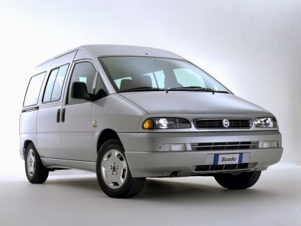
Here you will find the locations and schematics of the power distribution boxes. The fuses protecting the “Cigarette lighter” and “Fuel pump” circuits are highlighted in bold.
Passenger Compartment
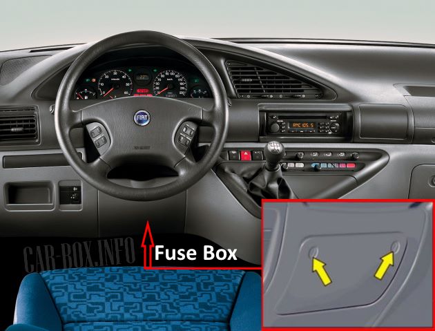
Left-hand drive models: The fuse box is located under the steering column, behind the lower trim panel. For right-hand drive vehicles, the power distribution box is situated behind the glove compartment on the passenger side.
Type 1

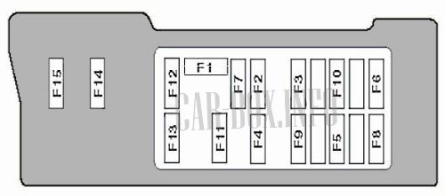
Overview of the Fiat Scudo interior fuse box.
| Diagram | ||
|---|---|---|
|
||
| No. | Description | A |
| F1 | 10 | |
| F2 | 25 | |
| F3 | 25 | |
| F4 | 10 | |
| F5 | 30 | |
| F6 | 5 | |
| F7 | 20 | |
| F8 | Central locking system | 20 |
| F9 | Heated seats | 20 |
| F10 | Ignition switch circuits | 10 |
| F11 | 5 | |
| F12 | 5 | |
| F13 | 5 | |
| F14 | 30 | |
| F15 | Rear window defogger | 30 |
Type 2
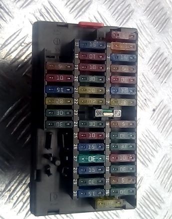
The photograph below serves as an example.
| Diagram | ||
|---|---|---|
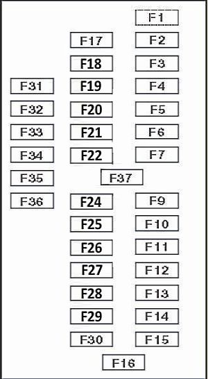
Schematic. |
||
| No. | Description | A |
| F1 | Audio system | 10 |
| F2 | 5 | |
| F3 | Spare | 15 |
| F4 | 5 | |
| F5 | 10 | |
| F6 | 15 | |
| F7 | Horn | 20 |
| F9 | 5 | |
| F10 | Spare | 30 |
| F11 | Spare | 30 |
| F12 | 10 | |
| F13 | Spare | 30 |
| F14 | Multifunction control module | 5 |
| F15 | 30 | |
| F16 | Cigarette lighter | 20 |
| F17 | 15 | |
| F18 | 10 | |
| F19 | 10 | |
| F20 | Spare | 30 |
| F21 | Heated seats | 20 |
| F22 | Spare | 20 |
| F24 | Windshield wipers / washers | 30 |
| F25 | 10 | |
| F26 | Turn signals and hazard warning lights | 15 |
| F27 | Rear window defogger | 30 |
| F28 | 15 | |
| F29 | Power windows | 30 |
| F30 | 15 | |
| F31 | Spare | - |
| F32 | Spare | - |
| F33 | Spare | - |
| F34 | Spare | - |
| F35 | Spare | - |
| F36 | Spare | - |
| F37 | - | - |
Engine Compartment
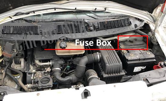
It is located adjacent to the battery. To access it, remove the protective cover.

Overview of one of the fuse box variants.
Type 1
| Diagram | ||
|---|---|---|

|
||
| No. | Description | A |
| F1 | Trailer wiring connector | 20 |
| F2 | Fuel pump module | 20 |
| F3 | Low beam headlight (left) | 10 |
| F4 | Low beam headlight (right) | 10 |
| F5 | Data Link Connector (DLC) | 10 |
| F6 | - | 10 |
| F7 | High beam headlight (left) | 10 |
| F8 | High beam headlight (right) | 10 |
| F9 | Radiator cooling fan motor | 25/40 |
| F10 | Headlight washer system | 30 |
| F11 | Auxiliary heater | 20 |
| F12 | Headlight washer system | 5 |
| F13 | Engine Control Module (ECM) | 15 |
| F14 | Anti-lock Braking System (ABS) | 30 |
| F15 | - | 40 |
| F16 | Radiator cooling fan motor | 30/50 |
| 1 | Fog light relay | |
| 2 | - | |
| 3 | Main ignition relay | |
| 4 | - | |
| 5 | - | |
| 6 | Headlight washer relay | |
| 7 | A/C relay | |
| 8 | ||
| 9 | - | |
| 10 | - | |
Type 2
| Diagram | ||
|---|---|---|

|
||
| No. | Description | A |
| F1 | Fuel pump | 20 |
| F2 | Headlights | 10 |
| F3 | 10 | |
| F4 | Headlight washer system | 25 |
| F5 | ||
| F6 | 10 | |
| F7 | Engine Control Module (ECM) | 10 |
| F8 | 20 | |
| F9 | 30 | |
| F10 | Spare | |
| F11 | Auxiliary heater | |
| F12 | High beam headlight (left) | 10 |
| F13 | High beam headlight (right) | 10 |
| F14 | Radiator cooling fan motors | 50 |
| F15 | 40 | |
| F16 | 70 | |
| F17 | 70 | |
| 1 | ||
| 2 | ||
| 3 | A/C relay | |
| 4 | ||
| 5 | Windshield wiper / washer relay | |
| 6 | Starter relay | |
| 7 | Main ignition relay | |
| 8 | ||
| 9 | A/C compressor clutch relay | |
