
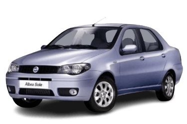
The Fiat Albea is a subcompact sedan produced by Fiat, primarily for the Eastern European market. An identical model was sold in the South American market under the name Fiat Siena. The vehicle is a sedan variant of the Palio hatchback. This article provides detailed fuse box diagrams for the first-generation (facelifted; chassis codes 178 / 172) Fiat Albea, covering the 2005, 2006, 2007, 2008, 2010, 2011, and 2012 model years.
Below, you will find the locations and photographs of the power distribution boxes. Fuses corresponding to the “Cigarette Lighter” and “Fuel Pump” are highlighted in bold.
Passenger Compartment
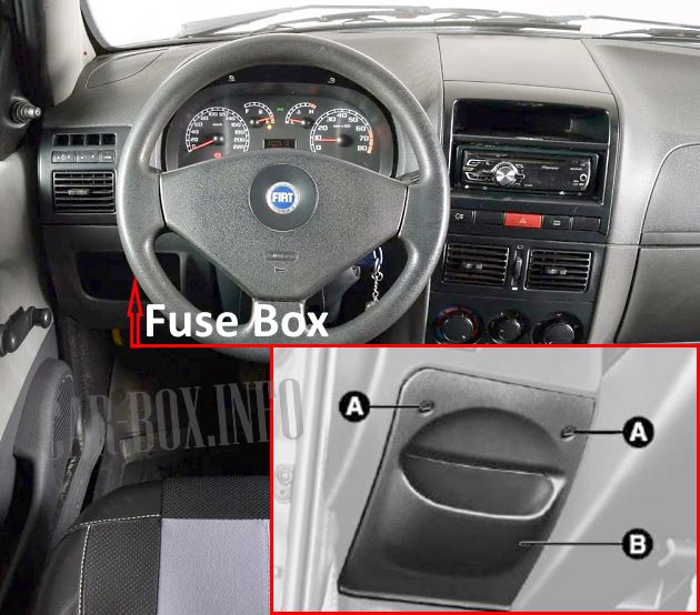
The interior fuse panel is located on the driver's side of the dashboard. To access the panel, remove the two retaining screws (A) and detach the protective cover (B).
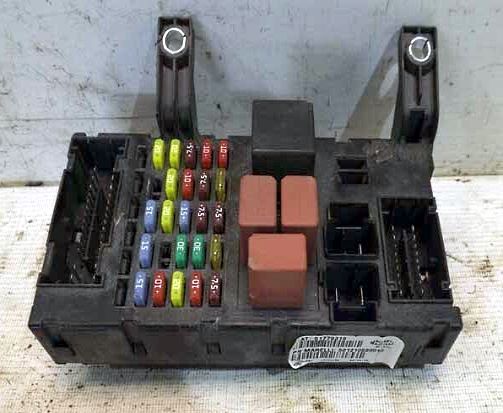
General view of the Fiat Albea / Fiat Siena interior fuse box.
| Diagram | ||
|---|---|---|
|
||
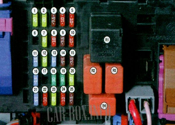
| No. | Description | A |
| 1 | Rear right power window | 10 |
| 2 | Front right power window | 20 |
| 3 | Ignition system | 7.5 |
| 4 | 10 | |
| 5 | Left low beam headlight | 10 |
| 6 | Spare | 25 |
| 7 | Rear left power window | 20 |
| 8 | Brake lights | 10 |
| 9 | Anti-lock Braking System (ABS) control module | 7.5 |
| 10 | Right low beam headlight | 10 |
| 11 | Heated seats | 15 |
| 12 | Front left power window | 20 |
| 13 | Parking lights | 15 |
| 14 | Airbag system (SRS) | 7.5 |
| 15 | License plate lights, HVAC control panel illumination, cigarette lighter, radio, ashtray illumination | 7.5 |
| 16 | Rear window wiper | 15 |
| 17 | Heated exterior side mirrors | 15 |
| 18 | Windshield wiper and washer system | 30 |
| 19 | Rear window defogger | 30 |
| 20 | Cigarette lighter | 10 |
| 21 | Subwoofer | 15 |
| 22 | Audio system / Radio | 10 |
| 23 | Central locking system | 20 |
| 24 | Hazard warning lights | 10 |
| 25 | Ignition system | 7.5 |
| R1 | Main relay | |
| R2 | Rear window defogger relay | |
| R3 | Ignition relay | |
| R4 | Low beam headlight relay | |
Engine Compartment
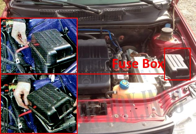
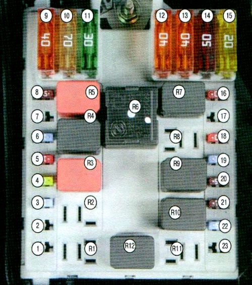
The fuse box is located next to the battery. To access it, pry the edge of the protective cover to remove it.

Photograph showing a typical engine compartment fuse block layout.
| Diagram | ||
|---|---|---|
|
||
| No. | Description | A |
| 1 | Spare | - |
| 2 | Spare | - |
| 3 | Engine Control Unit (ECU) | 15 |
| 4 | 20 | |
| 5 | 10 | |
| 6 | Fuel pump (fuel module) | 15 |
| 7 | Spare | - |
| 8 | Engine Control Unit (ECU) | 7.5 |
| 9 | Alternator | 40 |
| 10 | 70 | |
| 11 | Radiator cooling fan (Low speed) | 30 |
| 12 | Radiator cooling fan (High speed) | 40 |
| 13 | Anti-lock Braking System (ABS) | 40 |
| 14 | HVAC blower motor | 50 |
| 15 | Radiator cooling fan | 20 |
| 16 | Right high beam headlight | 10 |
| 17 | Spare | - |
| 18 | Left high beam headlight | 10 |
| 19 | Horn and cigarette lighter | 15 |
| 20 | A/C compressor | 7.5 |
| 21 | Fog lights | 7.5 |
| 22 | Ignition system | 15 |
| 23 | Spare | - |
| R1 | Spare | |
| R2 | Spare | |
| R3 | Ignition relay | |
| R4 | Fuel pump relay | |
| R5 | Radiator cooling fan relay (Low speed) | |
| R6 | Radiator cooling fan relay (High speed) | |
| R7 | High beam headlight relay | |
| R8 | Spare | |
| R9 | Horn and cigarette lighter relay | |
| R10 | Fog light relay | |
| R11 | Spare | |
| R12 | A/C compressor relay | |
