
The Fiat Bravo is a compact car developed by the Italian automaker Fiat and produced from 2007 to 2016. It serves as the direct successor to the Fiat Stilo. (Between 1995 and 2001, the original Bravo/Brava family was produced, from which the modern vehicle inherited its name.) This manual provides detailed fuse box diagrams for the Fiat Bravo (Fiat C-platform; chassis code 198) covering the 2007, 2008, 2009, 2010, 2011, 2012, 2013, 2014, 2015, and 2016 model years.
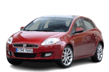
Fuses designated for the “Cigarette Lighter” and “Fuel Pump” are highlighted in bold.
In the engine compartment
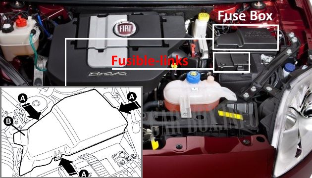
The engine compartment fuse box is located adjacent to the battery. To access the fuses, remove the protective cover (B) by releasing the three retaining clips (A). Additionally, a high-current fusible link panel is mounted directly to the positive battery terminal.
Fuse box
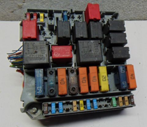
Example of the fuse block layout for models produced from June 2010 onward.
Type 1
Fiat Bravo models: 2010, 2011, 2012, 2013, 2014, 2015, and 2016.
| Diagram | ||
|---|---|---|
|
||
| No. | Description | A |
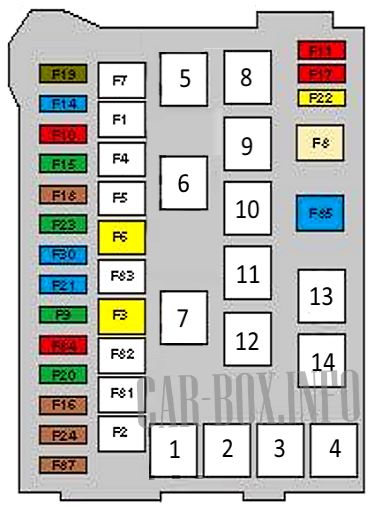
| F1 | Passenger compartment fuse box supply | 70 |
| F2 | 50 | |
| F3 | Ignition system circuits | 20 |
| F4 | Anti-lock Braking System (ABS) / Electronic Stability Program (ESP) | 40 |
| F5 | Electric Power Steering (EPS) | 70 |
| F6 | Radiator cooling fan motor | 20/30/40 |
| F7 | 40/50 | |
| F8 | HVAC blower motor | 40 |
| F9 | Headlamp washer pump | 30 |
| F10 | Horn | 10 |
| F11 | Engine management system | 10 |
| F14 | High beam headlamps | 15 |
| F15 | Auxiliary heater | 30 |
| F16 | Engine management system | 5 |
| F17 | 10/15 | |
| F18 | 5 | |
| F19 | Air conditioning system | |
| F20 | Transmission Control Module (TCM) | 30 |
| F21 | Spare | - |
| F22 | Engine management system | 15/20 |
| F23 | Anti-lock Braking System (ABS) / Electronic Stability Program (ESP) | 30 |
| F24 | Electric Power Steering (EPS) | 5 |
| F30 | Fog lamps | 15 |
| F81 | Glow plug control module | 60 |
| F82 | Auxiliary heater | 50 |
| F83 | Spare | - |
| F84 | Transmission Control Module (TCM) | 10 |
| F85 | Fuel pump module (Fiat Bravo fuel pump fuse) | 15 |
| F87 | Transmission Control Module (TCM) | 5 |
| 1 | High beam headlamp relay | |
| 2 | Horn relay | |
| 3 | A/C compressor clutch relay | |
| 4 | Starter motor signal (if equipped) | |
| 5 | Radiator cooling fan, high speed | |
| 6 | Radiator cooling fan, low speed | |
| 7 | — | |
| 8 | Engine management main relay | |
| 9 | HVAC blower motor relay | |
| 10 | Fuel pump relay (fuel module) | |
| 11 | Headlamp washer pump relay | |
| 12 | Left fog lamp | |
| 13 | Starter signal | |
| 14 | Right fog lamp | |
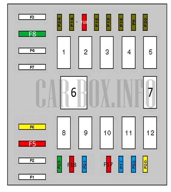
Type 2
Fiat Bravo models: 2006, 2007, 2008, 2009, and 2010.

General view.
| Diagram | ||
|---|---|---|
|
||
| No. | Description | A |
| F1 | Anti-lock Braking System (ABS) / Electronic Stability Program (ESP) | 40 |
| F2 | Body Control Module (BCM) / Instrument cluster | 50 |
| F3 | Main ignition circuits | 20 |
| F4 | Automated manual transmission control module | 30 |
| Headlamp washer pump (if equipped) | 30 | |
| F5 | Glow plug control module | 50 |
| F6 | Radiator cooling fan, low speed | 20/30/40 |
| F7 | Radiator cooling fan, high speed | 40/50 |
| F8 | HVAC blower motor | 30 |
| F9 | Fog lamps | 7.5 |
| F10 | Horn | 10 |
| F11 | Engine management system | 15 |
| F14 | Right high beam headlamp | 7.5 |
| F15 | Left high beam headlamp | 7.5 |
| F16 | Engine management, transmission | 7.5 |
| F17 | Engine management system | 10 |
| F18 | Engine management, transmission | 10 |
| F19 | Air conditioning system | 7.5 |
| F20 | Headlamp washer pump | 20 |
| F21 | Fiat Bravo fuel pump fuse | 15 |
| F22 | Engine management system | 15/20 |
| F23 | Anti-lock Braking System (ABS) / Electronic Stability Program (ESP) | 30 |
| F24 | Electric Power Steering (EPS) | 7.5 |
| F30 | Fog lamps | 7.5 |
| 1 | High beam headlamp relay | |
| 2 | HVAC blower motor relay | |
| 3 | Horn relay | |
| 4 | Fog lamps | |
| Left turn signal | ||
| 5 | Fog lamps | |
| Right turn signal | ||
| 6 | Radiator cooling fan, high speed | |
| 7 | A/C compressor clutch relay | |
| 8 | Radiator cooling fan, low speed | |
| 9 | Fuel pump relay | |
| 10 | Engine management main relay | |
| 11 | Automated manual transmission control module | |
| Headlamp washer pump relay (if equipped) | ||
| 12 | Headlamp washer pump relay | |
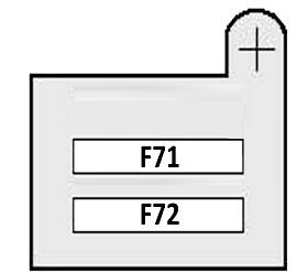
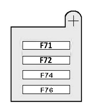
Power fuse panel
Located on the positive battery terminal.
| Diagram | ||
|---|---|---|
| No. | Description (Models from 06/2010) | A |
|
||
| F71 | Passenger compartment fuse box supply | 70 |
| F72 | 70 | |
| No. | Description (Models up to 06/2010) | A |
|
||
| F71 | Passenger compartment fuse box supply | 70 |
| F72 | Electric Power Steering (EPS) | 70 |
| F74 | Auxiliary heater | 30 |
| F76 | 50 | |
In the passenger compartment
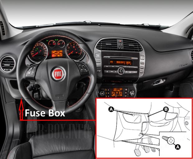
The fuse box is located behind a trim panel on the lower dashboard. To access the fuses, remove the protective cover (B) by extracting the three retaining screws (A).
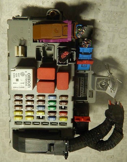
General view of the Fiat Bravo (Type 198) passenger compartment fuse box.
| Diagram | ||
|---|---|---|
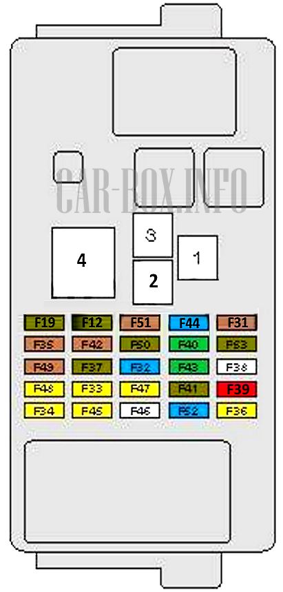
|
||
| No. | Description | A |
| F12 | Right low beam headlamp | 7.5 |
| F13 | Left low beam headlamp | 7.5 |
| F31 | HVAC blower relay / Manual climate control / Reversing lamps | 5 |
| F32 | Audio system | 15 |
| F33 | Power windows | 20 |
| F34 | 20 | |
| F35 | Reversing lamps, brake booster pressure sensor, mass airflow (MAF) sensor, clutch pedal switch, water-in-fuel sensor (diesel), brake light switch | 5 |
| F36 | Central locking system | 20 |
| F37 | HID (Xenon) headlamp control module, instrument cluster, center high-mounted stop lamp (CHMSL), brake light switch | 7.5 |
| F38 | — | |
| F39 | Rear dome lamp, OBD-II diagnostic connector, climate control system, Tire Pressure Monitoring System (TPMS), hazard warning flashers, Bluetooth module, audio system | 10 |
| F40 | Rear window defogger | 30 |
| F41 | Heated washer nozzles, heated exterior mirrors | 7.5 |
| F42 | Anti-lock Braking System (ABS) / Electronic Stability Program (ESP) | 5 |
| F43 | Windshield wiper/washer system, rear window washer | |
| F44 | Fiat Bravo cigarette lighter fuse, 12-volt power outlet | 15 |
| F45 | — | |
| F46 | Power sunroof | 20 |
| F47 | Power windows | 20 |
| F48 | 20 | |
| F49 | Heated front seats, rain/light sensor, power sunroof, alarm system control module, front dome lamp, steering wheel audio controls, Body Control Module (BCM), hazard flasher relay | 5 |
| F50 | Supplemental Restraint System (SRS) / Airbag control module | 7.5 |
| F51 | Climate control, audio system, cruise control, emissions control module, Bluetooth module, Air Quality Sensor (AQS), power exterior mirrors, TPMS module | 5 |
| F52 | Rear window wiper | 15 |
| F53 | Rear fog lamp, instrument cluster | 7.5 |
| 1 | Low beam headlamps, headlamp leveling system | |
| 2 | Heated windshield and rear window defogger relay | |
| 3 | Ignition auxiliary relay | |
| 4 | Power sunroof / power windows / main ignition relay | |
In the trunk
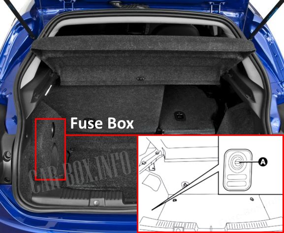
Located on the left side of the luggage compartment. To access the fuses, remove the protective trim panel (B) by releasing the retaining clips (A).
| Diagram | ||
|---|---|---|
| No. | Description | A |
| Vehicles produced from 06/2010 | ||

|
||
| F1 | Power seats | 30 |
| F2 | 30 | |
| F3 | Heated front seats | 10 |
| F4 | Spare | — |
| F5 | Spare | — |
| F6 | Heated front seats | 10 |
| 1 | Spare | |
| 2 | Spare | |
| 3 | Left power seat | |
| 4 | Right power seat | |
| Vehicles produced up to 05/2010 | ||
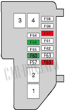
|
||
| F54 | Spare | — |
| F55 | Spare | — |
| F56 | Power seats | 30 |
| F57 | Spare | — |
| F58 | Spare | — |
| F59 | Spare | — |
| F60 | Power seats | 30 |
| F61 | Spare | — |
| F62 | Spare | — |
| F63 | Spare | — |
| F67 | Heated front seats | 10 |
| F68 | 10 | |
| 1 | Power seat relay | |
| 2 | Spare | |
| 3 | Spare | |
| 4 | Power seat relay | |

Can’t locate