
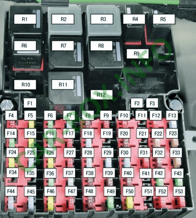
The fifth-generation Ford Fiesta was produced from 2002 through 2008. During this production run, the vehicle received a mid-cycle facelift, primarily updating its exterior styling. This publication details the location and function of the fifth-generation Ford Fiesta (B3 platform; chassis code B256) fuses and relays using photographs and block diagrams. The fuses for the cigarette lighter and power sockets are highlighted in bold.
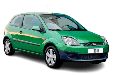
Fuse layouts and assignments may vary depending on the vehicle’s model year and equipment level.
Passenger Compartment Fuse Box
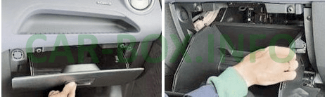
The main fuse and relay box is located in the passenger compartment, behind the glove box. To access it, press inward on both side walls of the glove box to release it.
| Diagram | |
|---|---|
|
|
| No. | Description |
| F1 | Spare |
| F2 | Trailer towing socket |
| F3 | Trailer towing socket |
| F4 | 10A Heating, ventilation, and air conditioning (HVAC) system |
| F5 | 20A Anti-lock braking system (ABS) |
| F6 | 30A Anti-lock braking system (ABS) |
| F7 | 15A Durashift EST transmission |
| F8 | 7.5A Power exterior mirrors |
| F9 | 10A Left low-beam headlamp |
| F10 | 10A Right low-beam headlamp |
| F11 | 15A Daytime running lights (DRL) |
| F12 | 15A Fuel injection system / Engine Control Unit (ECU) |
| F13 | 20A Engine management system (diesel) |
| F14 | 30A Starter motor |
| F15 | 20A Fuel pump |
| F16 | 3A Fuel injection relay / Engine Control Module (ECM) |
| F17 | 15A Main light switch |
| F18 | 15A Audio unit / car radio |
| F19 | 15A Daytime running lights (DRL) |
| F20 | 7.5A Instrument cluster, interior lighting delay timer, license plate lamps |
| F21 | Spare |
| F22 | 7.5A Left side marker / parking lamp |
| F23 | 7.5A Right side marker / parking lamp |
| F24 | 20A Central locking system and alarm horn |
| F25 | 15A Hazard warning lights |
| F26 | 20A Heated rear window, tailgate release |
| F27 | 15A Horn |
| F28 | 3A Battery sense, starter circuit |
| F29 | 15A Cigarette lighter |
| F30 | 15A Ignition system |
| F31 | 10A Main light switch |
| F32 | 7.5A Heated exterior mirrors |
| F33 | 7.5A Instrument cluster switch |
| F34 | Spare |
| F35 | 7.5A Heated front seats |
| F36 | 30A Power windows |
| F37 | 3A Anti-lock braking system (ABS) |
| F38 | 7.5A Generic Electronic Module (GEM) |
| F39 | 7.5A Airbag system (SRS) |
| F40 | 7.5A Automatic transmission control unit |
| F41 | Spare |
| F42 | 30A Heated windshield |
| F43 | 30A Heated windshield |
| F44 | 3A Audio unit / car radio |
| F45 | 15A Stop lamps / brake lights |
| F46 | 20A Windshield wipers and washer |
| F47 | 10A Rear window wiper |
| F48 | 7.5A Reversing lamps |
| F49 | 30A Blower motor |
| F50 | 20A Front fog lamps |
| F51 | 15A Auxiliary power socket |
| F52 | 10A Left high-beam headlamp |
| F53 | 10A Right high-beam headlamp |
| 15A fuse numbers 29 and 51 protect the cigarette lighter and auxiliary power socket circuits. | |
| Relay assignment | |
| R1 | 40A Power folding exterior mirrors |
| R2 | 40A Heated windshield |
| R3 | 70A Ignition circuit |
| R4 | 20A Low-beam headlamps |
| R5 | 20A High-beam headlamps |
| R6 | 20A Fuel pump |
| R7 | 40A Starter motor |
| R8 | 40A Electric heater blower |
| R9 | 20A Daytime running lights (DRL) |
| R10 | 20A Battery charging circuit |
| R11 | 40A Fuel injection system / ECU |
| R12 | Spare |
Engine Compartment Fuse Box
High-Power Fuse Panel
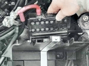
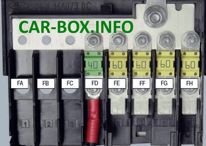
Mounted on the side of the battery housing along the positive battery lead, this panel consists of high-current mega-fuses. Accessing this panel requires removing the battery.
| Diagram | |
|---|---|
|
|
| No. | Designation |
| FA | 80A Auxiliary PTC heater |
| FB | 60A Transmission control module |
| FC | 60A Auxiliary PTC heater / diesel glow plugs |
| FD | 40A Engine cooling fan and A/C |
| FE | 60A Exterior lighting and Generic Electronic Module (GEM) |
| FF | 60A Ignition switch circuit |
| FG | 60A Engine control unit and lighting system |
| FH | 60A Heated windshield, ABS, ESP, power windows |
Relay Box
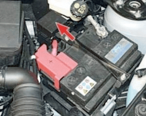
Located adjacent to the battery in a square enclosure.
| Diagram |
|---|

|
| R1 - A/C wide-open throttle (WOT) cut-off relay |
| R2 - Engine cooling fan (high speed) |
| R3 - Auxiliary PTC heater |
| R4 - Auxiliary PTC heater |
