The second generation Peugeot Partner, which was officially introduced in January 2008, made its debut at the Geneva Motor Show in March 2008. In this article we will understand in detail fuse box diagrams Peugeot Partner (2nd generation; B9 body, including Tepee modification) 2008, 2009, 2010, 2011, 2012, 2013, 2013, 2014, 2015, 2015, 2016, 2017, 2018, 2019, 2020 years of manufacture.
Here you will find the locations and photos of the mounting blocks. Also, we will separately mark the fuses responsible for the cigarette lighter and the fuel pump.
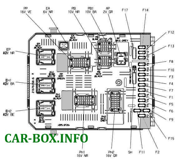
In the passenger compartment

Located on the left under the dashboard.
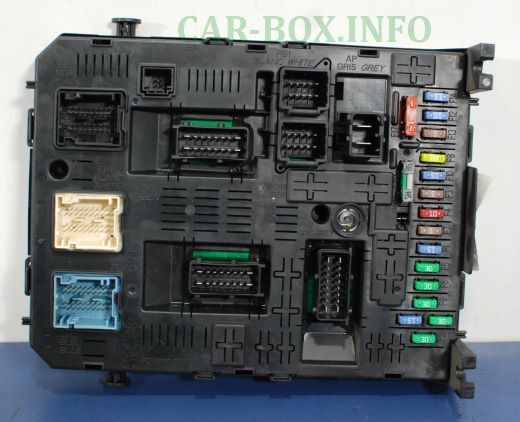
General view.
| Diagram | ||
|---|---|---|
|
||
| No. | Description | A |
| F1 | Rear window wiper | 15 |
| F2 | Empty | |
| F3 | Safety Airbag | 5 |
| F4 | Air conditioning, diagnostic socket, rear view mirror, headlight regulator | 10 |
| F5 | Window elevators | 30 |
| F6 | Door Locks | 30 |
| F7 | Rear plafond, front individual lighting plafond, sunroof | 5 |
| F8 | Car radio, CD changer, display, tire pressure monitoring unit, security alarm and siren | 20 |
| F9 |
|
30 |
| F10 | Upper part of the steering column | 15 |
| F11 | Ignition switch low current circuit | 15 |
| F12 | Rain and light sensor, safety airbag | 15 |
| F13 | Instrument panel | 5 |
| F14 | Parktronic, air conditioning control panel, hands-free system | 15 |
| F15 | Power supply to the locking system | 30 |
| F16 | Empty | |
| F17 | Heated rear window and mirrors | 40 |
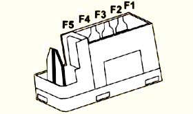
| Additional panel next to the main unit | ||
|
||
| F1 | Empty | - |
| F2 | Heated seats | 20 |
| F3 | Empty | - |
| F4 | Folding mirror relay | 15 |
| F5 | Socket relay for refrigerator connection | 15 |
The additional fuse box is designed for hitch and trailer. It is located behind the limiting partition on the right side. It is installed when the appropriate systems are in place.

|
||
| No. | Decoding | A |
| F1 | ignition switch relay, optional alternator | 15 |
| F2 | Trailer power supply 12V | 15 |
| F3 | DC power supply circuit for transformers | 15 |
| F4 | Emergency lights | 40 |
In the engine compartment
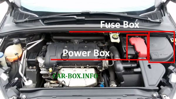
Location of the mounting blocks.
Fuse box
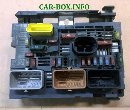
General view of the Peugeot Partner underhood fuse box.
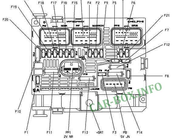
| Diagram | ||
|---|---|---|
|
||
| No. | Decoding | A |
| F1 | Engine control computer - power supply of the electric control unit for the two-speed group of the electric fan | 20 |
| F2 | sound alarm | 15 |
| F3 | front and rear washers | 10 |
| F4 | Headlight washers | 20 |
| F5 |
|
15 |
| F6 |
|
10 |
| F7 |
|
10 |
| F8 | starter coil | 25 |
| F9 | after contact protection interlocking module 3 relay - headlamp direction corrector motor | 10 |
| F10 | ignition coil control TU5JP4 - injector control TU5JP4 - power supply to the solenoid valve of the injection system pump DV6 | 30 |
| F11 | switching on the blower fan relay | 40 |
| F12 | front wiper low and high speed control | 30 |
| F13 | after contacting the CM power supply (intelligent service module) | 40 |
| F14 | Exhaust gas temperature recovery pump control | 30 |
| F15 | right high beam headlamp | 10 |
| F16 | left headlight high beam | 10 |
| F17 | left dipped beam | 15 |
| F18 | right dipped beam | 15 |
| F19 |
|
15 |
| F20 |
|
10 |
| F21 |
|
5 |
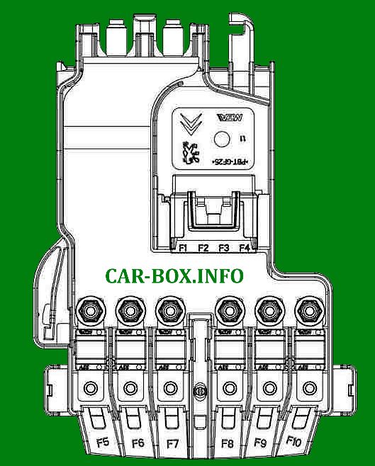
Power fuse panel
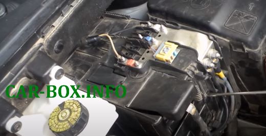
Example of accessing the power panel on the battery.
|
||
| No. | Description | A |
| F1 | Charging status module | 5 |
| F2 | Diagnostic connector | 15 |
| F3 | Resistance of brake pedal switches | 15 |
| F4 | Empty | |
| F5 | Power supply to the electric power steering pump group | 80 |
| F6 | Pre-post heating control module | 70 |
| F7 | Protection blocking module 3 relays | 100 |
| F8 | Empty | |
| F9 | Empty | |
| F10 | Simple motor protection relay | 30 |

Fuse for the horn?