In 2005, Hyundai introduced a completely updated Accent model. In some markets, this model was called Verna. The car was built on the same base as the Kia Rio. In this article, we will take a detailed look at the fuse box diagrams for the Hyundai Accent (third generation; index MC) 2005, 2006, 2007, 2008, 2009, 2010 and 2011 years of manufacture.

Here you will find the locations and photos of distribution boxes. The fuses responsible for the “Cigarette lighter” and “Fuel Pump” are highlighted in bold.
In the engine compartment
Depending on the type of engine installed (diesel or gasoline), there can be either one or two units.
Primary fuse box
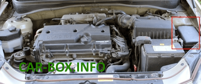
Located on the left side of the engine compartment.
Type 1
Vehicles from 2010.

General view.
| Diagram | ||
|---|---|---|

|
||
| № | Description | Amps |
| R1 | Fuel filter heater relay | |
| R2 | Blower relay | |
| R3 | Starter relay | |
| R4 | Condenser fan relay 1 | |
| R5 | Air-conditioning relay | |
| R6 | Horn relay | |
| R7 | Main relay | |
| R8 | Fuel pump relay | |
| R9 | Radiator fan relay | |
| R10 | Condenser fan relay 2 | |
| 1 | Spare | - |
| 2 | Radiator fan relay, Brake light switch, Condenser fan relay 2, Condenser fan relay 1, Air conditioning relay, Camshaft position sensor, Oxygen sensors | 10 |
| 3 | Gearbox oil cooling valve, Immobiliser control unit, Idle speed actuator, Canister purge solenoid, Fuel pump relay, Injectors (cylinders 1 – 4) | 15 |
| 4 | Powertrain control unit (PCM), Engine control unit | 20 |
| 5 | Air-conditioning control unit | 10 |
| 6 | Air-conditioning relay | 10 |
| 7 | Spare | - |
| 8 | Blower motor, Blower relay | 40 |
| 9 | Fuse and relay box in passenger compartment | 30 |
| 10 | Multi-purpose check connector, ESP control unit, ABS control unit | 40 |
| 11 | Multi-purpose check connector, ESP control unit, ABS control unit | 40 |
| 12 | Condenser fan relay 1 | 30 |
| 13 | Radiator fan relay, Condenser fan relay 1 | 30 |
| 14 | Fuel pump relay, Main relay | 30 |
| 15 | Fuse and relay box in passenger compartment | 50 |
| FL16 | Alternator | 125 |
| FL17 | EPS control unit | 80 |
| 18 | Fuse and relay box in passenger compartment | 30 |
| 19 | Ignition switch, Starter relay | 40 |
| 20 | Ignition switch | 30 |
| 21 | Relay box in passenger compartment (relay R2), Horn relay | 10 |
| 22 | Empty | - |
| 23 | Powertrain control unit (PCM), Engine control unit | 10 |
Type 2
Vehicles up to 2009.

General view.
| Diagram | ||
|---|---|---|

|
||
| № | Description | Amps |
| R1 | Horn relay | |
| R2 | Fuel filter heater relay | |
| R3 | Main relay | |
| R4 | Blower relay | |
| R5 | Fuel pump relay | |
| R6 | Starter relay | |
| R7 | Radiator fan relay | |
| R8 | Condenser fan relay 1 | |
| R9 | Condenser fan relay 2 | |
| R10 | Air-conditioning relay | |
| 1 | Powertrain control unit (PCM), Engine control unit | 20 |
| 2 | Immobilizer control unit, Transmission oil cooling valve, Idle speed drive, Injectors (cylinders 1 - 4), Canister purge solenoid | 15 |
| 3 | Oxygen sensors, Mass air flow meter, Air conditioning relay, Condenser fan relay 1, Condenser fan relay 2, Camshaft position sensor, Radiator fan relay | 10 |
| 4 | Multi-purpose check connector, ESP control unit, ABS control unit | 40 |
| 5 | Multi-purpose check connector, ESP control unit, ABS control unit | 40 |
| 6 | Fuse and relay box in passenger compartment | 30 |
| 7 | Blower relay, Blower motor | 40 |
| 8 | Air-conditioning relay | 10 |
| 9 | Air-conditioning control unit | 10 |
| 10 | EPS control unit | 80 |
| 11 | Generator | 125 |
| 12 | Fuse box in passenger compartment | 50 |
| 13 | Fuel pump relay, Main relay | 30 |
| 14 | Radiator fan relay, Condenser fan relay 1 | 30 |
| 15 | Condenser fan relay 1 | 30 |
| 16 | Ignition switch | 30 |
| 17 | Starter relay, Ignition switch | 40 |
| 18 | Fuse and relay box in passenger compartment | 30 |
| 19 | Powertrain control unit (PCM), Engine control unit | 10 |
| 20 | Empty | - |
| 21 | Security alarm system relay, Horn relay | 10 |
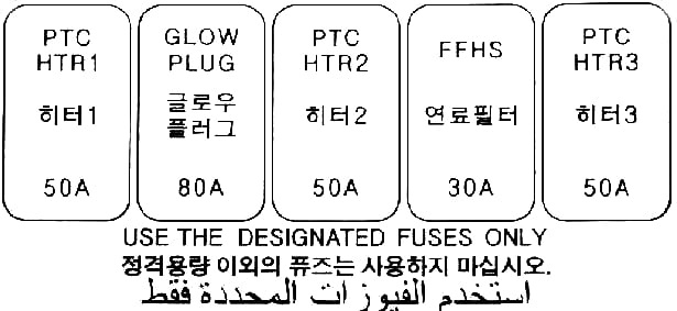
Additional box
Installed in models with diesel engines.
| Diagram | ||
|---|---|---|
|
||
| Name | Description | Amps |
| PTC HTR 1 | Heater | 50 |
| GLOW PLUG | Glow plug | 80 |
| PTC HTR 2 | Heater | 50 |
| FFHS | Fuel filter heating | 30 |
| PTC HTR 3 | Heater | 50 |
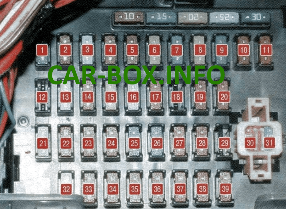
In the passenger compartment

Located at the bottom of the dashboard behind the protective cover.

General view of the Hyundai Accent III interior fuse box.
| Diagram | ||
|---|---|---|
|
||
| No. | Description | Amps |
| 1 | RR WIPER - Glass tailgate wiper | 15 |
| 2 | H / LP - Left headlight bulbs | 10 |
| 3 | FR WIPER - Windshield Wiper | 25 |
| 4 | BLOWER - Fan | 10 |
| 5 | H / LP (RH) - Right headlight bulbs | 10 |
| 6 | S / ROOF - Sunroof | 20 |
| 7 | STOP LP - Stop signals | 15 |
| 8 | C / DR LOCK - Central door lock switch | 20 |
| 9 | IGN COIL - Ignition Coil | 15 |
| 10 | ABS - Anti lock brake system | 10 |
| 11 | B / UPLP - Reversing light | 10 |
| 12 | BMS - Reserve | - |
| 13 | C / LIGHTER - Cigarette lighter fuse | 25 |
| 14 | FOLD'G - folding drive for exterior mirrors | 10 |
| 15 | HTR SEAT - Heated Seat | 20 |
| 16 | AMP - Amplifier | 25 |
| 17 | FR FOG LP - Fog lights | 10 |
| 18 | DRL - Daytime Running Lights | 10 |
| 19 | ECU - Engine management system | 10 |
| 20 | CLUSTER - Instrument panel | 10 |
| 21 | P / WDW RH - Power window lock (right side) | 25 |
| 22 | AUDIO - Audio system, trip computer | 10 |
| 23 | RR FOG LP - Rear fog lamp | 10 |
| 24 | IGN - Switch (ignition switch) | 10 |
| 25 | HTD GLASS - Heated rear window | 30 |
| 26 | A / BAG Airbag | 15 |
| 27 | TCU Automatic transmission control unit | 10 |
| 28 | SNSR - Sensors | 10 |
| 29 | SPARE | - |
| 30 | MULT B / UP Air conditioning control unit, clock, interior lighting ETACS | 10 |
| 31 | AUDIO Audio system | 15 |
| 32 | P / WDW LH Locking power windows (left side) | 25 |
| 33 | HTD MIRR Heated exterior mirrors | 10 |
| 34 | TAIL LP (LH) Left tail light | 10 |
| 35 | TAIL LP (RH) Right rear side light | 10 |
| 36 | HAZARD - Alarm | 10 |
| 37 | T / SIG LP - Turn Signal Lights | 10 |
| 38 | A / BAG IND - Airbag warning lamp | 10 |
| 39 | START - Red Starter relay | 10 |

Relay modules on the back of the unit.

Description:
- R1 - Front fog light relay;
- R2 - Power window relay;
- R3 - Rear heater relay;
- R4 - Rear fog light relay;
- R5 - Door unlock relay;
- R6 - Door unlock relay.
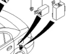
A separate brake light relay is located at the rear, near the taillight control box.

Thank you to all those in charge of this excellent site, your brother from Algeria
Thank you for this information.it the best I found to describe all the relays and fuses I am a female trying to figure out my electrical system cuz it all worked. And now nothing turns on so that uou
Fuel gauge fuse