
The Hyundai Accent (sold in select markets as the Hyundai Verna) is a subcompact car manufactured by the South Korean automaker Hyundai Motor Company. This guide details the fuse box diagrams, relay layouts, and power distribution systems for the second-generation Hyundai Accent (LC chassis code, model years 1999–2006).

Below you will find power distribution box locations, wiring diagrams, and component photos. The fuses for the “Cigarette Lighter” and “Fuel Pump” are highlighted in bold for easy identification.
In the Engine Compartment
Depending on the engine option (gasoline or diesel), the vehicle is equipped with either one or two fuse and relay boxes in the engine bay.
Main Fuse Box
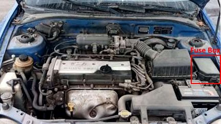
Located on the left (driver’s) side of the engine bay, adjacent to the battery.
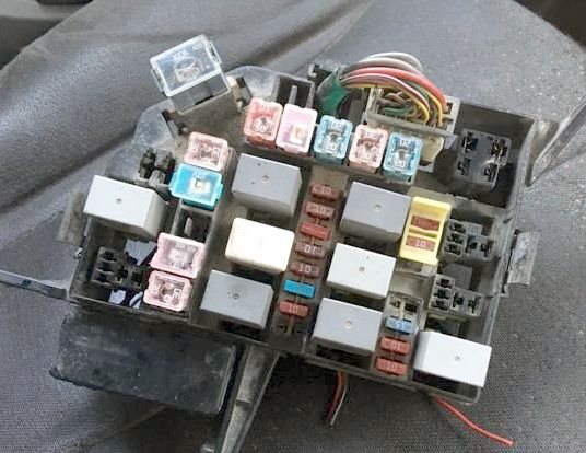
General view.
| Diagram | ||
|---|---|---|
|
||
| No. | Description | Amps |
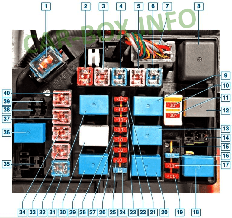
| 1 | Alternator / Generator main fuse | 100 |
| 2 | Central locking, anti-theft alarm, brake lamps, rear window defogger, warning chime, interior illumination, Electronic Control Module (ECM) | 50 |
| 3 | Parking lamps, main headlight circuit | 20 |
| 4 | Engine Control Module (ECM) | 20 |
| 5 | Ignition switch, starter circuit | 30 |
| 6 | Radiator cooling fan | 20 |
| 7 | Wiring harness connector / Spare | - |
| 8 | Blower motor relay | - |
| 9 | Horn relay | - |
| 10 | Interior lamps / Dome light | 10 |
| 11 | Audio head unit / Radio player | 10 |
| 12 | A/C condenser fan relay No. 2 | - |
| 13 | A/C compressor clutch relay | - |
| 14 | Front fog lamp relay | - |
| 15 | Fuel pump relay | - |
| 16 | Idle Air Control (IAC) valve, Camshaft Position (CMP) sensor | 15 |
| 17 | Engine Control Module (ECM) power feed | 10 |
| 18 | Radiator cooling fan relay | - |
| 19 | Air conditioning control circuit | 10 |
| 20 | A/C condenser fan relay No. 1 | - |
| 21 | Engine Control Module (ECM) memory / constant power | 10 |
| 22 | A/C compressor magnetic clutch | 10 |
| 23 | Horn | 10 |
| 24 | Front fog lamps | 15 |
| 25 | Left headlight (low/high beam) | 10 |
| 26 | Right headlight (low/high beam) | 10 |
| 27 | Right tail/parking lamps, license plate lamps | 10 |
| 28 | Left tail/parking lamps, headlight washer relay control | 10 |
| 29 | Parking light relay | - |
| 30 | Alternator pre-excitation resistor | - |
| 31 | Starter solenoid relay | - |
| 32 | A/C condenser fan motor | 20 |
| 33 | Power windows main fuse | 30 |
| 34 | Anti-lock Braking System (ABS) valve power | 30 |
| 35 | Daytime Running Lights (DRL) / Low beam headlight relay | - |
| 36 | Fuel pump relay control circuit | - |
| 37 | Anti-lock Braking System (ABS) pump motor | 30 |
| 38 | Diode block | - |
| 39 | Diode block | - |
| 40 | Blower motor fuse | 30 |
Auxiliary Fuse Box (Diesel Models)
Installed exclusively on models equipped with a diesel engine.
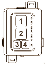
Description:
1 – Glow plug relay (80A);
2 – Auxiliary coolant heater relay No. 1 (60A);
3 – Auxiliary coolant heater relay No. 2 (30A);
4 – Fuel filter heater relay (30A)
In the Passenger Compartment
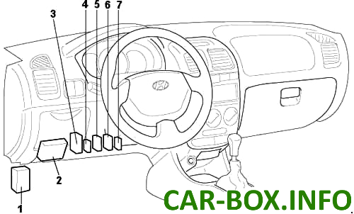
Component Layout:
1 – Interior fuse box;
2 – Interior relay box;
3 – ETACS (Electronic Time and Alarm Control System) module or rear defogger relay;
4 – Rear window wiper relay (Hatchback models);
5 – Seat belt warning timer module (without ETACS);
6 – Intermittent wiper relay (without ETACS);
7 – Door chime module / key warning buzzer.
Fuse Box
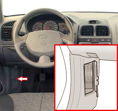
Located on the driver’s side kick panel below the dashboard, behind a removable protective cover panel.
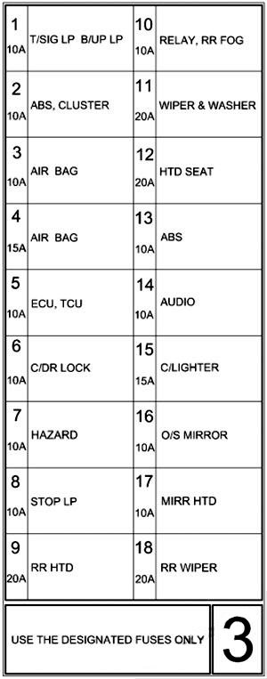
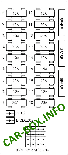
Sample diagram decal from the fuse box cover.
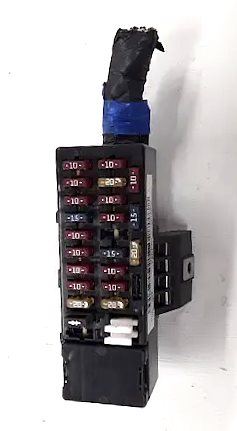
General view of the Hyundai Accent LC interior fuse panel.
| Diagram | ||
|---|---|---|
|
||
| No. | Description | A |
| 1 | Turn signal indicators, reverse light switch, Transmission Range (TR) switch, automatic transmission shift lever lock | 10 |
| 2 | Instrument cluster gauges, ETACM (Electronic Time & Burglar Alarm Control Module), alternator pre-excitation resistor, seat belt warning timer | 10 |
| 3 | Instrument cluster indicator lights | 10 |
| 4 | Supplemental Restraint System (SRS / Airbags) | 15 |
| 5 | Engine Control Module (ECM), Powertrain Control Module (PCM), A/T selector lever switch, Transmission Range switch, Mass Air Flow (MAF) sensor, Vehicle Speed Sensor (VSS), fuel filter warning lamp | 10 |
| 6 | Central power door locking system | 10 |
| 7 | Hazard warning lamps, ETACM (Electronic Time & Burglar Alarm Control Module) | 10 |
| 8 | Brake lamps, automatic transmission shift interlock solenoid, shift range indicator | 10 |
| 9 | Rear window defogger (grid heater) | 20 |
| 10 | Headlamp leveling system, power windows, headlight washers, ETACM, front fog lamps, A/C condenser fan, radiator cooling fan, fuel filter heater relay, rear window washer motor | 10 |
| 11 | Windshield wiper and washer motor | 20 |
| 12 | Heated front seats | 20 |
| 13 | Anti-lock Braking System (ABS) control module feed | 10 |
| 14 | Digital clock, audio system head unit, automatic transmission shift position indicator | 10 |
| 15 | Cigarette lighter / auxiliary 12V power outlet fuse | 15 |
| 16 | Power side mirrors | 10 |
| 17 | Heated rear window relay coil, heated side mirrors | 10 |
| 18 | Rear window wiper motor | 20 |
Relay Box
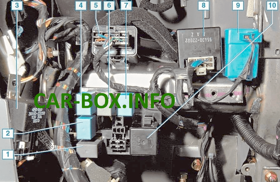
The interior relay box is positioned behind the driver-side lower dash storage bin / coin pocket. To gain access, open the tray, squeeze the side retaining tabs inward, and hinge the compartment down to release it from its clips.
| Diagram | |
|---|---|
|
|
| No. | Description |
| 1 | Electronic Brake-force Distribution (EBD) relay |
| 2 | Rear fog lamp relay |
| 3 | Main engine control system / ECM relay (mounting bracket unbolted for illustration clarity) |
| 4 | Headlamp control relay |
| 5 | Windshield wiper and washer interlock relay |
| 6 | Anti-lock Braking System (ABS) relay |
| 7 | Power window main relay |
| 8 | Rear window defogger relay |
| 9 | Horn relay |
| 10 | Turn signal indicator and hazard flasher relay |

thanks