Daily is a family of light-duty trucks and passenger buses of small capacity, produced by the Italian company Iveco S.p.A. One of the oldest models of the concern, the first generation appeared in 1978. In this article, we will take a detailed look at the fuse box diagrams for the Iveco Daily (2nd Gen; second restyling) 2011, 2012, 2013, 2014 years of manufacture.
Here you will find the locations and photos of distribution boxes. The fuses responsible for the “Cigarette lighter” and “Fuel Pump” are highlighted in bold.
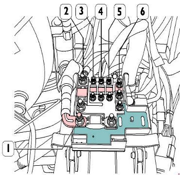
In the engine compartment
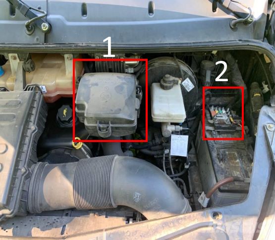
Component locations: 1- main fuse box #1; 2 - power pack (on battery)
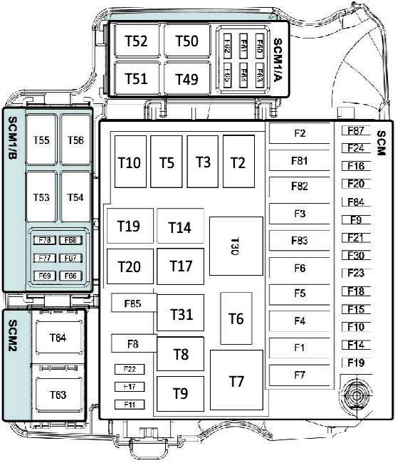
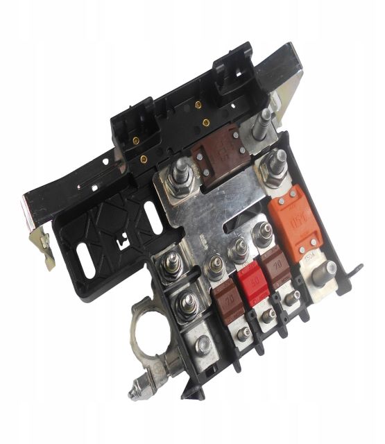
Fuse box #1
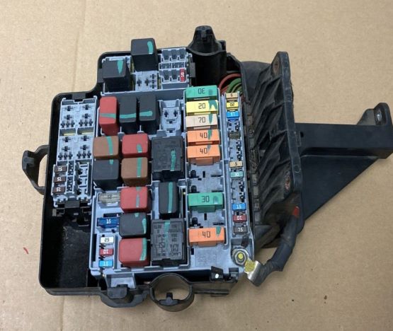
General view.
| Diagram | ||
|---|---|---|
|
||
| No. | Amps | Description |
| T02 | 20 A | BOSCH cooling pump |
| T02 | 20 A | Baruffaldi coupling from tee (CNG) |
| Т03 | 30 A | Side marker lamps relay |
| T05 | 30 A | First gear Baruffaldi coupling |
| T06 | 20 A | Horn relay |
| T07 | 50 A | Ignition switch discharge |
| T08 | 20 A | Iveco Daily 5 Fuel pump relay |
| T09 | 30 A | MAIN RELAY |
| T10 | 30 A | Preventing engine start |
| T14 | 20 A | Second gear Baruffaldi coupling |
| T14 | 20 A | Cylinder solenoid valves (CNG) |
| T17 | 10/20 A | Windscreen wiper 1or 2nd speed |
| T19 | 10/20 A | Indscreen wiper speed activation |
| T20 | 20 A | Diagnostics with MODUS |
| Т30 | 50 A | Cab heating fans |
| T31 | 30 A | Fuel filter heater and sediment filter |
| F01 | 40 A | Pneumatic suspension |
| F02 | 30 A | Ignition switch |
| F03 | 40 A | Cab climate control fans and auxiliary engine coolant heater |
| F04 | 30 A | Braking system (valves) |
| F05 | 40 A | Air suspensions |
| F06 | 40 A | SCM 1 /А - SCM 1 /В - SCM2 power supply |
| F07 | 40 A | Relay T7 for resetting the ignition switch power supply |
| F08 | 15 A | Fuel pump relay T8 |
| F09 | 30 A | Automatic transmission |
| F11 | 15 A | Relay T64 (30-87) for heated exterior mirrors and heated windshield |
| F11 | 15 A | EDC FI A (primary loads) from MAIN RELAY injectors (CNG) |
| F14 | 10 A | Automatic transmission - MAIN RELAY T9 (86) |
| F15 | 10 A | T2 relay (30-87) for BOSCH cooling pump |
| F16 | 15 A | Iveco Daily Cigarette lighter fuse |
| F17 | 10/15 A | EDC FIC (secondary loads) from MAIN RELAY Smart Drive Unit (CNG) |
| F18 | 30 A | Rear differential lock |
| F19 | 7,5 A | T6 relay (30-87) for horn |
| F20 | 10 A | 13 pin socket |
| F21 | 7,5 A | TI4 relay (30) for cylinder solenoid valves (CNG) |
| F22 | 20 A | EDC F1A and F1C (primary loads) from MAIN RELAY - lambda probe |
| F22 | 15 A | Waste gate (CNG) - lambda probes (CNG) |
| F23 | 30 A | T19 relay (30-87) for wipers |
| F24 | 15 A | Power socket from T7 |
| F30 | 7,5 A | T3 relay (30-87) for side marker lamps |
| F81 | 30 A | Automatic transmission |
| F82 | 70 A | Body computer second power |
| F83 | 40 A | Relay T30 (30-87) of heater fans inside the cabin |
| F84 | 15 A | Cylinder supply solenoid valve |
| F84 | 7,5 A | T5 and T14 relays for Baruffaldi coupling |
| F85 | 25 A | T31 relay (30-87) for fuel filter and sediment filter heater |
| F87 | 7,5 A | EDC - automatic transmission |
| F87 | 7,5 A | 5SF - automatic transmission |
| SCM2 board | ||
| T63 | - | Empty |
| T64 | 20 A | Heated exterior mirrors - heated windscreen |
| SCM1/B board | ||
| T53 | 20 A | Unit heater |
| T54 | 20 A | Headlight washers |
| T55 | 10/20 A | Power Take Off |
| T56 | 10/20 A | Stop lights with activated retarder TELMA |
| F66 | 15 A | Headlight washer relay T54 (30-87) |
| F67 | - | Empty |
| F68 | - | Empty |
| F69 | 5 A | Optional 4448 for bus |
| F77 | - | Empty |
| F78 | - | Empty |
| SCM1/A board | ||
| T49 | 30 A | Stop-start relay |
| T50 | - | Empty |
| T51 | 20 A | Activating the compressor from the climate control |
| T52 | 20 A | Rear windows heater |
| F60 | 30 A | Supplementary climate control system |
| F61 | 7,5 A | T51 relay (30-87) for air conditioner compressor |
| F62 | 10 A | Right rear window heater relay T52 (30-87) |
| F63 | 10 A | Heated rear left window heater - self-contained heater - compressor relay T56 (86) |
| F64 | 5 A | IBS sensor for Stop & Start |
| F65 | 20 A | Seat heating relay T7 (30-87) |
Fuse box #2 (on the battery)
General view.
| Diagram | ||
|---|---|---|
|
||
| No. | Amps | Description |
| 1 | 500 A | +30 from F75 for starter, alternator and retarder (if available) |
| 2 | 150 A | +30 from F70 for SCM BUS-BAR |
| 3 | 60 A | +30 from F73 for pre-heating glow plugs |
| 4 | 40 A | +30 from F72 for brake unit |
| 5 | 80 A | +30 from F7I for Ist Body Computer power |
| 6 | - | +30 to F64 in SCM/A for IBS sensor for Stop & Start |
In the passenger compartment
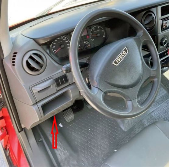
Located behind the plastic cover on the left side of the dashboard.
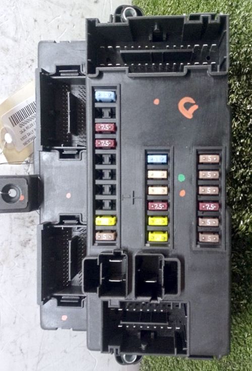
General view of the Iveco Daily interior fuse box.
| Diagram | ||
|---|---|---|

|
||
| No. | Amps | Description |
| F12 | 7,5 A | right dipped beam headlight |
| F13 | 7,5 A | left dipped beam headlight - headlight corrector |
| F31 | 5 A | headlight washers and electric motors and controls for power windows |
| F32 | 7,5 A | battery removal at minimum voltage - interior lighting |
| F33 | 15 A | Sliding door |
| F34 | 20 A | 12V power outlet |
| F36 | 15 A | MODUS car radio - tachograph - convergence - siren - parking sensor |
| F37 | 7,5 A | Instrument panel - stop lights - trailer socket |
| F38 | 20 A | Central locking system |
| F42 | 5 A | ABS or ESP system |
| F43 | 20 | windscreen washer |
| F47 | 25 | driver's side power window |
| F48 | 25 | passenger side power window |
| F49 | 5 | Control panel - tachograph - ASR control - Thelma (coil) - video camera - locking rear differential |
| F50 | 5 | Safety Airbag system |
| F51 | 5 | Green filter - car radio - toe-in - parking sensors -CAF |
| F53 | 5 | Instrument panel - auxiliary heater timer |
| F89 | - | Empty |
| F90 | 7,5 | left beam headlight |
| F91 | 7,5 | right high beam headlight |
| F92 | 7,5 | left fog light |
| F93 | 7,5 | right fog light |
| No. | Relay modules | |
| Т25b | Power windows on driver's side (down) | |
| Т26а | Power window on passenger side (up) | |
| Т26b | Power window on passenger side (down) | |
| Т37а | Rear doors central closing | |
| Т37b | Central closing (common) | |
| Т37с | Central closing of side doors | |
| T37d | Central closing of rear doors | |
| Т44 | Battery removal with minimum voltage | |
| T01а | Left dipped beam headlight - headlight corrector | |
| T01b | Right dipped beam headlight | |
| Т11а | Left high beam headlight | |
| T11b | Right high beam headlight | |
| Т12а | Left fog light | |
| Т12b | Right fog light | |
| Т23а | Windscreen washer | |
| Т25а | Power windows on driver's side (up) | |
