Iveco Daily of the third generation is produced since 2014. It is a modernized version of the previous generations, keeping the same engine range. In 2015, the vehicle received the award "Van of the Year in Europe". In 2019 went through a restyling: ADAS systems and LED daytime running lights were added. In this article, we will take a detailed look at the fuse box diagrams for the Iveco Daily (3rd Gen) 2014, 2015, 2016, 2017, 2018, 2019, 2020, 2021 years of manufacture.
Here you will find the locations and photos of distribution boxes. The fuses responsible for the “Cigarette lighter” and “Fuel Pump” are highlighted in bold.
In the passenger compartment
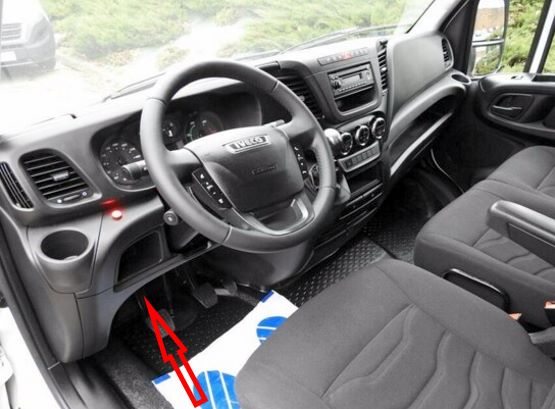
Located behind the cover on the left side of the dashboard.
General view of the Iveco Daily interior fuse box.
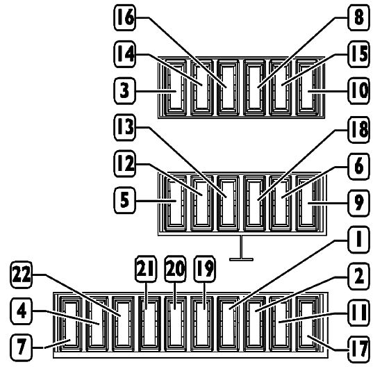
| Diagram | ||
|---|---|---|
|
||
| No. | Amps | Description |
| 1 | - | Empty (internal protection) |
| 2 | - | Empty (internal protection) |
| 3 | 5 A | Power windows and mirror switch; Heating; Air conditioning; Windshield washer; Headlight washer; Heated rear window and windshield; |
| 4 | - | Empty (internal protection) |
| 5 | 15 A | 13-pin socket and trailer; Tachograph; TGC. EOBD connector; Anti-theft system; ZF 8HP 70L transmission control unit. |
| 6 | 20 A | +30 power supply to the radio; Iveconnect; Voltage stabilizer. |
| 7 | 15 A | Power supply + 30; Air conditioning; Differential locking |
| 8 | 7.5 A | +15 power brake light switch (brake pedal); Dashboard. |
| 9 | 20 A | +30 power supply to central locking |
| 10 | 5 A | Power +15 ABS controller; Speed sensor. |
| 11 | 20 A | Power + 30 / A washer pump |
| 12 | 25 A | Power window on the driver’s side |
| 13 | 25 A | Power window on the passenger side |
| 14 | 5 A | Power supply + 15 different control units; EM; Swing doors; Steering angle sensor. Trailer socket and control unit; Tachograph; Air conditioning; 13-pin connector; Differential locking system |
| 15 | 5 A | Power +15 / Airbag system |
| 16 | 5 A | Power + 15 Automatic transmission; Reverse light; LDWS; USB port; Open door vehicle unlocking; Voltage stabilizer (S&S system); Interior temperature sensor; Parking sensors; Radio; Clutch pedal (S&S system); TRM; 24 - 12V power. |
| 17 | 5 A | + 30 / A power supply to the instrument panel. |
| 18 | 7.5 A | horn (beep) |
| 19 | - | Empty (internal protection) |
| 20 | - | |
| 21 | 7.5 A | Left fog lamp |
| 22 | 7,5 A | Right fog lamp |
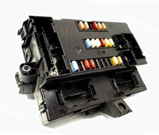
In the engine compartment
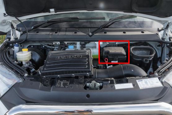
Located on the center of the engine bay, behind the plastic cover.
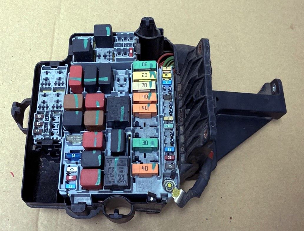
General view.
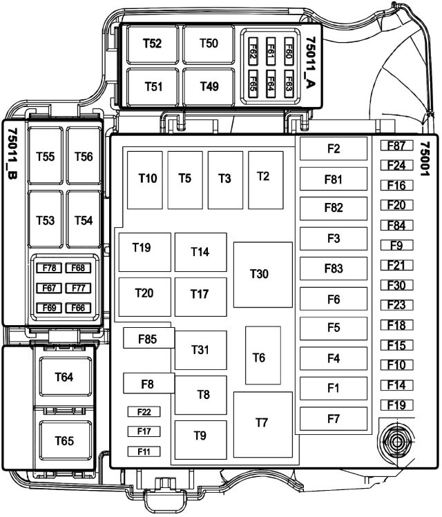
| Diagram | ||
|---|---|---|
|
||
| No. | Amps | Description |
| F1 | 40 A | Air suspension solenoid valves |
| F2 | 40 A | 8 HP fan |
| F3 | 30 A | PTO |
| F4 | 30 A | Braking system (ESP) |
| F5 | 40 A | ECAS control unit and air suspension valves |
| F6 | 40 A | Mains fuses (F61) (F62) (F66) |
| F7 | 40 A |
|
| F8 | 15 A | Iveco Daily fuel pump fuse |
| F9 | – | – |
| F10 | 15 A | Heated exterior mirrors; Heated windscreen. |
| F11 | 15 A | Main EDC loads from the main relay |
| F14 | 10 A | Main motor starter relay |
| F15 | 10 A | Bosch cooling pump (for F1C Euro 5 engines) |
| F16 | 15 A | Cigarette Lighter |
| F17 | 10 A | EDC secondary loads from the main relay |
| F18 | 15 A | Power take-off and EM |
| F19 | – | – |
| F20 | 15 A | Power take-off and EM |
| F21 | – | – |
| F22 | 25 A | Main EDC loads from the main relay |
| F23 | 30 A | Windshield wipers |
| F24 | 20 A | Power outlet |
| F30 | 5 A | Side position lights |
| F60 | 20 A | Seat heating |
| F61 | 30 A | Rear differential lock |
| F62 | 30 A | Rear window heating |
| F63 | 10 A | ECAS control unit; Scavenge; Air conditioning compressor. |
| F64 | 15 A | Urea (for F1C Euro VI engines) |
| F65 | 20 A | Urea (for F1C Euro VI engines) |
| F66 | 15 A | Headlight washers (versions with manual gearbox) |
| 20 A | Transmission oil cooling fan (versions with automatic transmission 8 hp) | |
| F67 | 7.5 A | Trailer socket |
| F68 | 10 A | Windshield heating |
| F69 | 7.5 A | Heated mirrors |
| F77 | 5 A | Heater (not VENDOR and VENDOR F1A versions) |
| 15 A | Heated swing window | |
| F78 | 7.5 A | Trailer socket |
| F81 | – | Empty |
| F82 | 70 A | Second Body Computer power supply |
| F83 | 40 A | Cab internal fans |
| F84 | 7.5 A | Baruffaldi connector |
| F85 | 25 A | Fuel and particulate filter heater |
| F87 | 5 A | Vacuum sensor (Start & Stop); Motor controller; 8HP automatic gearbox control unit. |
| T02 | 20 A | Bosch cooling pump;Starter (Start & Stop). |
| T03 | 20 A | Side position lights |
| T05 | 20 A | Baruffaldi connector |
| T06 | – | Empty |
| T07 | 50 A | Ignition switch discharge |
| T08 | 20 A | Fuel pump |
| T09 | 30 A | Main Relay |
| T10 | 30 A | Prevent the engine from starting; +50 signal to Start&Stop system. |
| T14 | 30 A | Baruffaldi clutch (low speed) |
| T17 | 10 – 20 A | Wiper (1st and 2nd speed) |
| T19 | 10 – 20 A | Windshield wiper on |
| T20 | 20 A | EOBD diagnostics |
| T30 | 50 A | Internal cabin fans |
| T31 | 30 A | Fuel filter heater |
| T49 | 20 A | Urea or the Start & Stop system |
| T50 | 20 A | Heated windscreen and mirrors |
| T51 | 20 A | Switching on the compressor from the air conditioner |
| T52 | 30 A | Rear window heating |
| T53 | 20 A | Heater (not VENDOR and VENDOR F1A versions) |
| 20 A | Heated swing window | |
| T54 | 10 – 20 A | Battery cut-off (safety relay) |
| T55 | 10 – 20 A | Battery cut-off (activation signaling) |
| T56 | – | Empty |
| T64 | 20 A | Headlight washers (manual gearbox) |
| 30 A | Transmission oil cooling fan (automatic transmission versions) | |
| T65 | 10 – 20 A | Automatic transmission fan |
