
The Land Rover Freelander is a compact crossover SUV produced since 1997. In 2003, the model received a facelift featuring redesigned side mirrors, revised headlamps, and clear turn signal lenses integrated into the rear bumper light assemblies. This article provides detailed fuse box diagrams and relay assignments for the first-generation Land Rover Freelander (L314 chassis) produced for model years 1997 through 2006.

Below you will find the locations, wiring diagrams, and layout photos of the power distribution boxes. Fuses for the “Cigarette Lighter” and “Fuel Pump” circuits are highlighted in bold.
Engine Compartment
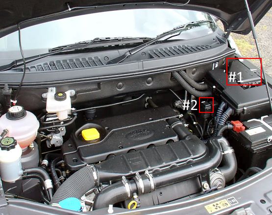
1. Main fuse box
2. Auxiliary fuse box (vehicles with heated windscreen or PTC heater)
Main Fuse Box
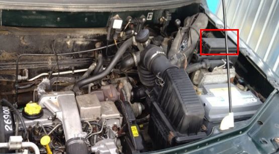
Fuse box location (1997–2002 model years).
2003–2006 Model Years
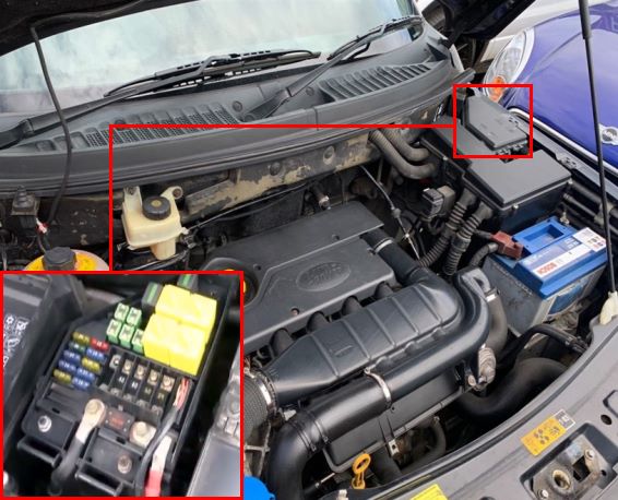
Fuse box location.
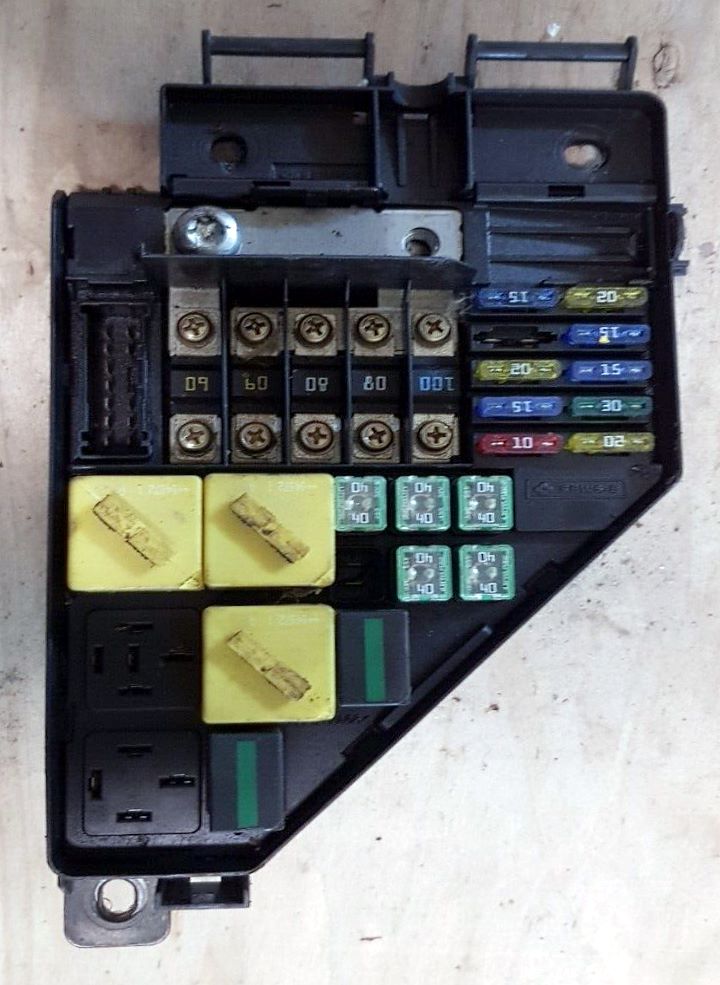
General view.
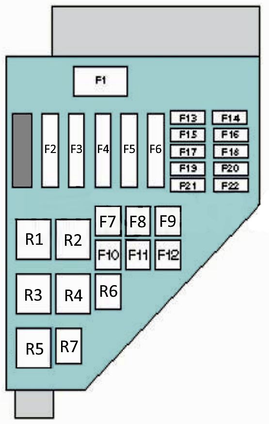
| Diagram | ||
|---|---|---|
|
||
| No. | Description | Rating |
| F1 | Alternator | 150 A |
| F2 | Ignition switch | 60 A |
| F3 | 60 A | |
| F4 | Power windows, passenger compartment fuse box, heated rear window, Central Control Unit (CCU) | 80 A |
| F5 | Engine cooling fan motor | 40 A |
| F6 | Glow plug system | 100 A |
| F7 | Starter motor solenoid | 40 A |
| F8 | Anti-lock braking system (ABS) module | 40 A |
| F9 | Passenger compartment fuse box, main beam headlamps | 40 A |
| F10 | Not used | 40 A |
| F11 | Anti-lock braking system (ABS) pump | 40 A |
| F12 | Headlamp switch | 40 A |
| F13 | Diesel glow plug relay | 15 A |
| F14 | Engine management system (EMS) | 20 A |
| F15 | 15 A | |
| F16 | Air conditioning (A/C), engine cooling fan, automatic transmission control module (TCM) | 15 A |
| F17 | Engine management system (EMS) | 20 A |
| F18 | Horn | 15 A |
| F19 | Hazard warning lights | 15 A |
| F20 | A/C and heater blower motor | 30 A |
| F21 | Air conditioning (A/C) compressor clutch | 10 A |
| F22 | Inertia fuel shut-off (IFS) switch (petrol engines) | 20 A |
| Relays | ||
| R1 | Fuel pump relay (petrol) | |
| R2 | Starter motor relay | |
| R3 | Stop lamps (brake lights) relay | |
| R4 | Engine management system (EMS) relay | |
| R5 | Not used | |
| R6 | Horn relay | |
| R7 | A/C compressor clutch relay | |
1997–2002 Model Years
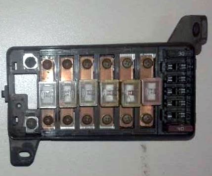
General view of the fuse box.
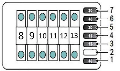
| Diagram | ||
|---|---|---|
|
||
| No. | Description | Rating |
| 1 | Engine cooling fan | 40 A |
| 2 | Not used | — |
| 3 | Horn | 15 A |
| 4 | Hazard warning lights | 15 A |
| 5 | Fuel injectors, fuel pump | 20 A |
| 6 | A/C condenser fan | 40 A |
| 7 | Starter motor solenoid | 30 A |
| 8 | Alternator | 120 A |
| 9 | Ignition supply 1 | 60 A |
| 10 | Passenger compartment fuse box | 60 A |
| 11 | Ignition supply 2 | 60 A |
| 12 | Lighting circuits | 60 A |
| 13 | ABS pump | 30 A |
Auxiliary Fuse Box

Description:
1. PTC heater or heated windscreen (left side) – 30 A
2. PTC heater or heated windscreen (right side) – 30 A
3. PTC heater or switch illumination – 30 A / 7.5 A
4. Not used
Passenger Compartment
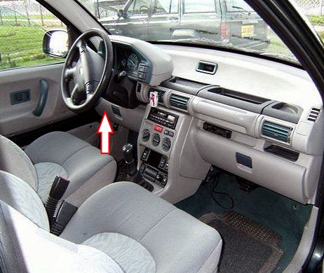
Located behind the glove box.
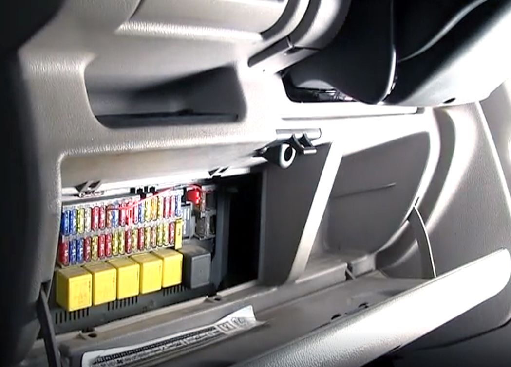
To access the fuses, open the glove box, press the two retaining latches, and remove the plastic access panel.
2000–2006 Model Years
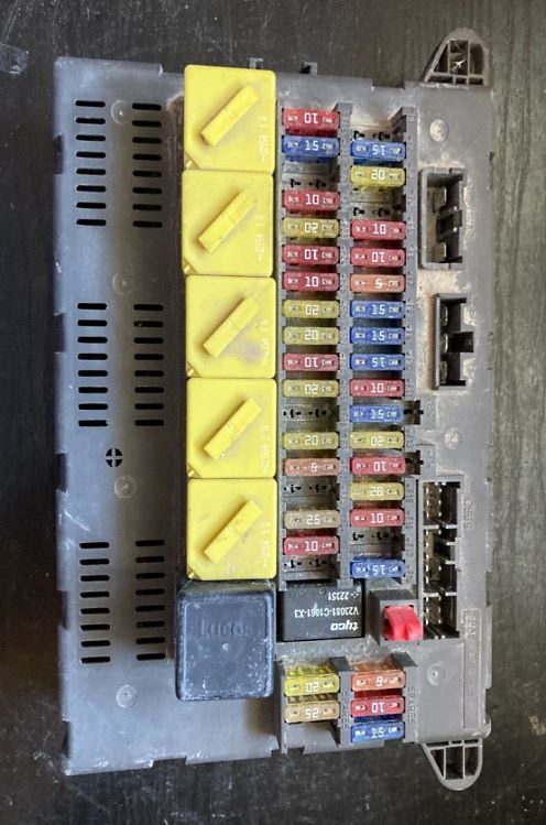
General view.
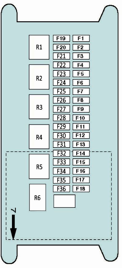
| Diagram | ||
|---|---|---|
|
||
| No. | Description | Rating |
| F1 | Rear window washer, power door mirrors | 15 A |
| F2 | Stop lamps (brake lights), reversing lamps | 15 A |
| F3 | Windscreen wiper/washer system, Central Control Unit (CCU) | 15 A |
| F4 | A/C and heater blower control unit | 25 A |
| F5 | Engine immobilizer, cooling fan relay, instrument cluster | 10 A |
| F6 | Engine management system (EMS) | 10 A |
| F7 | Hazard warning lights, Anti-lock Braking System (ABS) | 5 A |
| F8 | Turn signal indicators, CCU, instrument cluster | 15 A |
| F9 | Audio system, cigarette lighter | 10 A |
| F10 | Cigarette lighter | 15 A |
| F11 | Audio system, Central Control Unit (CCU) | 10 A |
| F12 | Electric sunroof | 15 A |
| F13 | Auxiliary 12V power socket | 20 A |
| F14 | Audio system, Data Link Connector (DLC/OBD2), clock, power mirrors, interior lighting | 5 A |
| F15 | Central locking system, Central Control Unit (CCU) | 20 A |
| F16 | Audio system, number plate lamps, instrument cluster, CCU, right side/tail lamps | 10 A |
| F17 | Power door mirrors | 10 A |
| F18 | Right headlamp (main beam) | 15 A |
| F19 | Alternator | 10 A |
| F20 | Left headlamp (main beam) | 15 A |
| F21 | Not used | 15 A |
| F22 | Rear fog lamps | 10 A |
| F23 | Heated rear window | 20 A |
| F24 | Left headlamp (dipped beam) | 10 A |
| F25 | Right headlamp (dipped beam) | 10 A |
| F26 | Left rear power window switch | 20 A |
| F27 | Right rear power window switch | 20 A |
| F28 | Headlamp leveling, left side/tail lamps | 10 A |
| F29 | Heated front seats | 20 A |
| F30 | Rear window wiper motor | 10 A |
| F31 | Tailgate power window motor | 20 A |
| F32 | Engine immobilizer | 5 A |
| F33 | Power window control module, left front power window switch | 20 A |
| F34 | Right front power window switch | 20 A |
| F35 | Engine management system (EMS), Hill Descent Control (HDC) – 1.8L | 10 A |
| F36 | Supplemental Restraint System (SRS) / Airbags | 10 A |
| 1 | Headlamp main beam relay | |
| 2 | Heated rear window relay | |
| 3 | Auxiliary power socket relay | |
| 4 | Sunroof motor relay | |
| 5 | Power window circuit relay | |
| 6 | Turn signal indicator relay | |
| 7 | Central Control Unit (CCU) relay | |
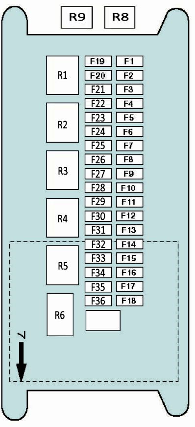
1997–2000 Model Years
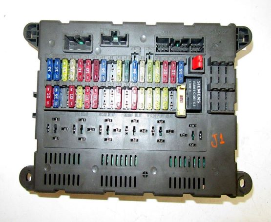
General view.
| Diagram | ||
|---|---|---|
|
||
| No. | Description | Rating |
| F1 | Power mirrors, rear window washer | 15 A |
| F2 | Reversing lamps, stop lamps (brake lights) | 15 A |
| F3 | Windscreen wiper/washer system | 15 A |
| F4 | Heater / air conditioning (A/C) | 25 A |
| F5 | Starter motor | 10 A |
| F6 | Engine management system (EMS) | 10 A |
| F7 | Anti-lock braking system (ABS) | 10 A |
| F8 | Turn signal indicators, hazard warning lights, instrument cluster lamps | 15 A |
| F9 | Not used | — |
| F10 | Cigarette lighter | 20 A |
| F11 | Audio system | 10 A |
| F12 | Electric sunroof | 10 A |
| F13 | Auxiliary 12V power socket | 25 A |
| F14 | Anti-theft alarm system, Data Link Connector (DLC/OBD2), audio system, interior lamps | 10 A |
| F15 | Central locking system | 20 A |
| F16 | Right headlamp leveling, instrument cluster illumination, right side/tail lamps | 10 A |
| F17 | Power door mirrors | 10 A |
| F18 | Right headlamp (main beam) | 15 A |
| F19 | Fuel filler flap solenoid, fuel pump fuse | 10 A |
| F20 | Left headlamp (main beam) | 15 A |
| F21 | Not used | — |
| F22 | Rear fog lamps | 10 A |
| F23 | Heated rear window | 20 A |
| F24 | Left headlamp (dipped beam) | 10 A |
| F25 | Right headlamp (dipped beam) | 10 A |
| F26 | Not used | — |
| F27 | Not used | — |
| F28 | Instrument cluster illumination, left headlamp leveling, left side/tail lamps | 10 A |
| F29 | Not used | — |
| F30 | Rear window wiper/washer | 10 A |
| F31 | Tailgate power window motor | 20 A |
| F32 | Anti-lock braking system (ABS) | 20 A |
| F33 | Left front power window switch | 20 A |
| F34 | Right front power window switch | 20 A |
| F35 | Not used | — |
| F36 | Supplemental Restraint System (SRS) / Airbags | 10 A |
| Relays | ||
| R1 | Headlamp main beam relay | |
| R2 | Heated rear window relay | |
| R3 | Auxiliary power socket relay | |
| R4 | Sunroof relay | |
| R5 | Power window circuit relay | |
| R6 | Turn signal indicator relay | |
| R7 | Central Control Unit (CCU) relay | |
| R8 | Stop lamp (brake light) relay | |
| R9 | ABS pump motor relay | |
