
Production of the second-generation Range Rover began in September 1994, 24 years after the introduction of the original model. The vehicle was equipped with an updated version of the Rover V8 engine alongside a 2.5-liter BMW M51 turbocharged inline six-cylinder diesel engine. This article provides detailed fuse box diagrams and relay assignments for the Land Rover Range Rover (Second generation; chassis code P38A) for the 1994 through 2002 model years.
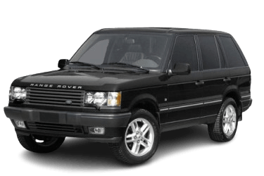
Below you will find the locations and diagrams for the power distribution boxes. Fuses designated for the “Cigarette Lighter” and “Fuel Pump” are highlighted in bold.
Engine Compartment

Located in the engine bay adjacent to the battery, beneath the protective cover.
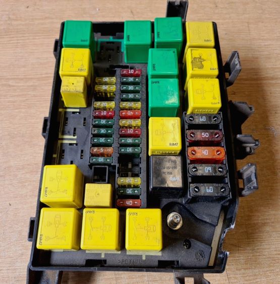
General view.
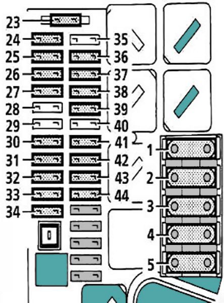
| Diagram | ||
|---|---|---|
|
||
| No. | Description | Rating |
| 1 | Unused | 60 A |
| 2 | Spare | 50 A |
| 3 | ABS Hydraulic Pump | 40 A |
| 4 | Unused | 60 A |
| 5 | Unused | 60 A |
| 23 | Supplemental Restraint System (SRS) / Airbag Module | 10 A |
| 24 | ABS Control Module | 5 A |
| 25 | Headlamp Washers, Front Wipers | 20 A |
| 26 | Engine Management System (EMS) | 20 A |
| 27 | A/C Compressor Clutch | 10 A |
| 28 | Ignition Coils (Petrol) | 30 A |
| Cooling Fan (Diesel) | 15 A | |
| 29 | Electronic Air Suspension (EAS) | 10 A |
| 30 | Heated Windscreen | 30 A |
| 31 | Air Conditioning (A/C) | 30 A |
| 32 | Heated Windscreen | 30 A |
| 33 | Diagnostic Port, Battery Backed-Up Sounder (BBUS) | 5 A |
| 34 | Heater Blower Motor | 30 A |
| 35 | Electronic Air Suspension (EAS), Air Conditioning | 10 A |
| 36 | Air Conditioning (A/C) | 30 A |
| 37 | Engine Management System (EMS) | 30 A |
| 38 | Anti-Lock Braking System (ABS) | 30 A |
| 39 | Fuel Pump | 20 A |
| 40 | Electronic Air Suspension (EAS), Starter Motor | 40 A |
| 41 | Horns | 20 A |
| 42 | HVAC / Heating & Ventilation, Key Interlock Solenoid | 10 A |
| 43 | Heater Blower Motor | 30 A |
| 44 | Engine Management System (EMS) | 30 A |
Passenger Compartment

The interior fuse box (BeCM) is located beneath the front passenger seat, behind the access panel cover.
| Diagram | ||
|---|---|---|

|
||
| No. | Description | Rating |
| 1 | Instrument Cluster, Radio, Clock, Center Console Switchpack | 10 A |
| 2 | Heated Seats (Left/Right), Right Rear Power Window | 30 A |
| 3 | EAT ECU (Automatic Transmission) - Battery Feed | 5 A |
| 4 | Transfer Box ECU - Battery Feed | 30 A |
| 5 | Unused | - |
| 6 | Auto-Dimming Rearview Mirror, Illuminated Sun Visors, Auxiliary Switched Ignition Feed 1 | 10 A |
| 1994–1999: Transfer Box ECU Ignition Feed / EAT ECU Ignition Feed | ||
| 7 | 1994–1999: Airbag Control Module (SRS) | 10 A |
| 1999–2002: Transfer Box ECU Ignition Feed / EAT ECU Ignition Feed | ||
| 8 | Front Cigarette Lighter, Auxiliary Phone, Radio, HEVAC Module | 30 A |
| 1994–1999: Antenna / Aerial Amplifier | ||
| 9 | Left & Right Front Door Outstations / Battery Feed 2 | 20 A |
| 10 | Right Power Seat (Lumbar, Cushion, Backrest, Headrest, Forward/Reverse Controls) | 30 A |
| 11 | Spare | - |
| 12 | Left Rear Power Window, Heated Rear Screen | 30 A |
| 13 | Sunroof, Gearshift Interlock Solenoid | 20 A |
| 1994–1999: Ignition Key Lock Solenoid | ||
| 14 | Left & Right Rear Door Central Locking, Fuel Filler Flap Release, Trailer Auxiliary Battery Feed | 30 A |
| 15 | Left & Right Rear Audio Amplifiers (ICE), Subwoofer, Right Tail Lamp, Interior/Cargo Area Lighting, Remote Audio Controls, Rear Door Central Locking, Rear Wiper | 20 A |
| 16 | Unused | 30 A |
| 17 | Brake Light Switch Feed | 10 A |
| 1994–1999: Electronic Air Suspension (EAS) Switches, HEVAC Ignition Signal | ||
| 18 | 6th Door Outstation Battery Feed (Not Fitted) | 30 A |
| 19 | Unused | - |
| 20 | Left Power Seat (Lumbar, Cushion, Backrest, Headrest, Forward/Reverse Controls) | 30 A |
| 21 | Unused | - |
| 22 | Left & Right Front Power Windows | 30 A |

i almost miss pin assignment for the controls
am a technical car repair man from tanzania
i prefer to see your support for the africans car repair men for providing the best diagrams and more
we support your market and please support us too