The 2006 Lexus LS460 with the XF40 body is the fourth generation of the luxury LS series sedan, which debuted in 1989. The new generation was unveiled to the public at the Detroit Auto Show in January 2006, shortly after the LF-Sh hybrid concept car was unveiled, showcasing the main features of the new flagship. In this material, we will analyze in detail the fuse diagrams Lexus LS 460 (XF40 - USF40, USF45) 4th generation 2006, 2007, 2008, 2009, 2010, 2011, 2012, 2013, 2014, 2015, 2016, 2017 release.
Here you will find the locations and photos of distribution boxes. The fuses responsible for the “Cigarette lighter” and “Fuel Pump” are highlighted in bold.
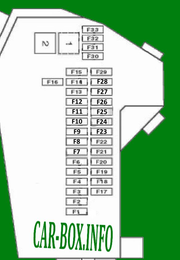
In the passenger compartment
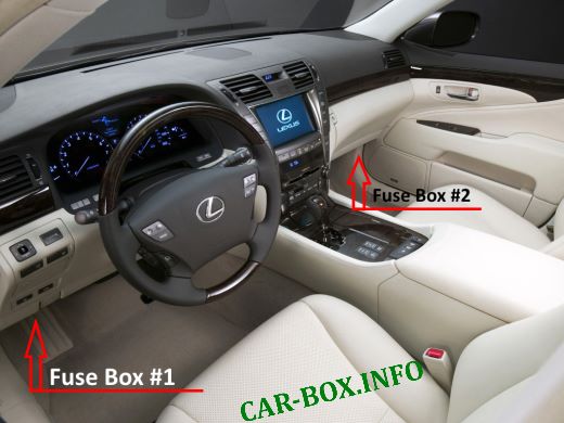
Location of components: # 1 - driver side fuse block, # 2 - passenger side fuse block
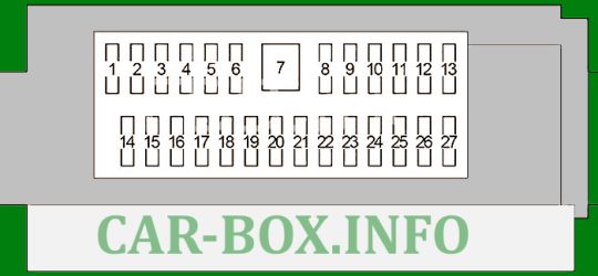
Fuse box #1
No. 1 on the picture.
| Diagram | ||
|---|---|---|
|
||
| No. | Description | A |
| 1 | Instrument cluster, front seat settings, rear seat settings, steering column tilt and height adjustment, central locking, cruise = control | 10 |
| 2 | Clock, interior lighting | 10 |
| 3 | Audio system | 10 |
| 4 | Fuel tank hatch, audio system, interior lighting | 10 |
| 5 | - | - |
| 6 | Keyless entry system with start button, anti-theft system | 5 |
| 7 | Audio amplifier | 30 |
| 8 | Steering wheel lock | 20 |
| 9 | central locking | 10 |
| 10 | Alarm and direction indicators | 10 |
| 11 | Rear door from the driver's side (lights, lock, power window) | 25 |
| 12 | Front door on the driver's side (lighting, electric mirrors, lock blocking, power windows, heated mirrors) | 25 |
| 13 | Brake light | 5 |
| 14 | Automatic transmission, central locking, cruise control, heated rear window, sunroof, belt pretensioner, brakes, head restraints, socket, turn signals, climate control unit, audio system | 10 |
| 15 | Cruise control system | 5 |
| 16 | Starting system, heated and ventilated seats | 15 |
| 17 | Body electronics module, seat belt pretensioner, starting system, steering column tilt and height adjustment | 5 |
| 18 | Socket | 15 |
| 19 | central locking | 5 |
| 20 | - | - |
| 21 | Sunroof | 30 |
| 22 | Steering column tilt and height adjustment system | 30 |
| 23 | central locking | 5 |
| 24 | Diagnostic connector | 10 |
| 25 | Driver seat settings | 30 |
| 26 | Heated and ventilated driver's seat | 20 |
| 27 | Heated and ventilated rear seat from the driver's side | 30 |
Fuse box #2
#2 on the picture.
| Diagram | ||
|---|---|---|

|
||
| No. | Decoding | A |
| 1 | Steering column tilt and height adjustment system, keyless entry system with start button, instrument cluster, power control unit, Lexus link system | 5 |
| 2 | Diagnostics, Lexus link system | 5 |
| 3 | Central locking, front seat settings, rear seat settings, variable ratio steering (VGRS), keyless entry system with start button, start system, parking assist | 10 |
| 4 | - | - |
| 5 | Air suspension | 20 |
| 6 | central locking | 10 |
| 7 | Audio amplifier | 30 |
| 8 | Navigation, air conditioning, Lexus link system | 20 |
| 9 | Power control unit | 5 |
| 10 | Light switch, wiper and washer, horn, tilt and height adjustment of the steering column, power windows, central locking, blinds in the doors, rear blind, rear seat settings, buttons on the steering wheel | 5 |
| Light switch, wiper and washer, horn, tilt and height adjustment of the steering column, power windows, central locking, blinds in the doors, rear blind, rear seat settings, buttons on the steering wheel | 10 | |
| 10 | central locking | 10 |
| 12 | Rear door on the passenger side (lighting, lock, power window) | 25 |
| 13 | Front door on the passenger side (lighting, power mirrors, lock, power window, heated mirrors) | 25 |
| 14 | Radio cassette | 5 |
| 15 | Variable Gear Ratio Steering (VGRS) | 5 |
| 16 | Audio system, navigation, central locking, variable ratio steering (VGRS), air conditioning, head restraints, seat belt pretensioner, park assist, tire pressure monitoring system | 10 |
| 17 | Heated and ventilated seats | 10 |
| 18 | Cigarette lighter fuse Lexus LS 460 | 15 |
| 19 | Audio system, navigation, clock, Lexus link system, cruise control system | 5 |
| 20 | - | - |
| 21 | - | - |
| 22 | Air conditioning system | 10 |
| 23 | Heated and ventilated passenger seat | 20 |
| 24 | Front passenger seat settings | 30 |
| 25 | Rear Seat Settings, Passenger Side | 30 |
| 26 | Front passenger seat settings | 30 |
| 27 | Heated and ventilated rear seat on the passenger side | 30 |
In the engine compartment
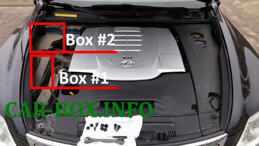
Location of components.
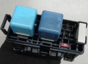
Fuse box #1

example photo.
| Diagram | ||
|---|---|---|

|
||
| No. | Appointment | A |
| 1 | Heated parking area for wiper blades | 25 |
| 2 | Wiper | 30 |
| 3 | ABS, VSC, VDIM | 10 |
| 4 | Keyless entry system with start button | 25 |
| 5 | Power steering | 10 |
| 6 | High beam, horn | 30 |
| 7 | Intelligent headlamp control (AFS), high beam, front side light, horn, siren, windshield washer, headlight washers | 10 |
| 8 | Charging system, power steering, cooling fan, intelligent headlamp control (AFS) | 10 |
| 9 | Left low beam | 15 |
| 10 | ABS system | 10 |
| 11 | Right low beam | 15 |
| 12 | Multiport fuel injection system / sequential multiport fuel injection system | 10 |
| 13 | Cruise control system | 10 |
| 14 | Multiport fuel injection system / sequential multiport fuel injection system, braking system, airbags | 10 |
| 15 | Multiport fuel injection system / sequential multiport fuel injection system, stop lamps, safety belts with preventive function, charging system | 10 |
| 16 | Fuses: "ECU-B", "D MPX-B 1", "D MPX-B 2", "P MPX-B", "RR MPX-B 1", "RR MPX-B 2", "DOME" | 30 |
| 17 | Main beam, front side light, horn, siren, windshield washer, headlight washers, seat belts with preventive function | 10 |
| 18 | Air fuel ratio sensor | 15 |
| 19 | Multiport fuel injection system / sequential multiport fuel injection system | 25 |
| 20 | Windshield washer, siren, headlight washers, front side light | 20 |
| 21 | Multiport fuel injection system / sequential multiport fuel injection system | 25 |
| 22 | Fuel system | 10 |
| 23 | Front fog light | 15 |
| 24 | Air conditioner, cooling fan | 10 |
| 25 | Headlight range control | 10 |
| 26 | Fuses: "P IG2", "P RR-IG2" | 10 |
| 27 | - | - |
| 28 | Injectors | 10 |
| 29 | - | - |
| 30 | - | - |
| 31 | - | - |
| 32 | Fuses: "P MPX-B", "RR ECU-B", "RR MPX-B1", "RR MPX-B2" | 30 |
| 33 | Brake system | 5 |
| 34 | ABS system | 10 |
| 35 | Multiport fuel injection system / sequential multiport fuel injection system | 25 |
| 36 | 25 | |
| 37 | 10 | |
| 38 | 10 | |
| 39 | Starter | 30 |
| 40 | ABS system | 50 |
| 41 | 50 | |
| 42 | Variable valve timing system | 40 |
| Relay | ||
| R1 | Ignition (IG2 / IG1) | |
| R2 | ||
| R3 | Engine control unit (EFI MAIN2) | |
| R4 | Fuel pump relay (C / OPN / F / PMP) | |
| R5 | ||
| R6 | (VVT LH) Variable valve timing system | |
| R7 | (EFI MAIN) Engine control unit | |
| R8 | (ST CUT) Starter | |
| R9 | (VVT RH) Variable valve timing system | |
| R10 | (ST) Starter | |
Fuse box #2
No. 2 on the picture.
| Diagram | ||
|---|---|---|
|
||
| No. | Protected circuit | A |
| F1 | Headlight washer pump | 30 |
| F2 | Additional heater | 50 |
| F3 | 40 | |
| F4 | ^ 08/08 Capacitor | 40 |
| F5 | Heater blower motor | 50 |
| F6 | ^ 08/08: Air Suspension | 40 |
| F7 | - | 30 |
| F8 | Battery power distribution | 50 |
| F9 | ^ 08/08: Additional heater | 60 |
| F10 | Battery power distribution | 80 |
| F11 | - | 80 |
| F12 | Cooling fan motor | 80 |
| F13 | ^ 08/08: Battery Power Distribution | 60 |
| F14 | Battery power distribution | 180 |
| F15 | - | - |
| F16 | - | - |
| F17 | ^ 08/08: Not used | - |
| F18 | Battery power distribution | 30 |
| F19 | Power steering control unit | 40 |
| F20 | Battery power distribution | 40 |
| F21 | 40 | |
| F22 | 40 | |
| F23 | 30 | |
| F24 | (40A) ^ 08/08: Engine management system | 40 |
| F25 | ^ 08/08: Not used | - |
| F26 | - | - |
| F27 | 80 | |
| F28 | Engine management system | 80 |
| F29 | ^ 08/08: Power steering | 80 |
| F30 | Auxiliary heater | 25 |
| F31 | 25 | |
| F32 | Battery control module | 5 |
| F33 | - | |
| Relay | ||
| 1 | cooling fan | |
| 2 | air suspension | |
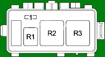
Additional relay blocks
Description.
| Block #1 | |
|
|
|
|
| No. | Protected circuit |
| 1 | No |
| R1 | Heated parking area for wiper blades (DEICER) |
| R2 | ABS (ABS MTR2) |
| R3 | Heated rear window (DEFOG) |
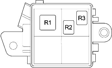
| Block #2 | |
|
|
| No. | Protected circuit |
| R1 | PTC heater No. 2 |
| R2 | PTC heater No. 1 |
| R3 | PTC heater no. 3 |
In the trunk
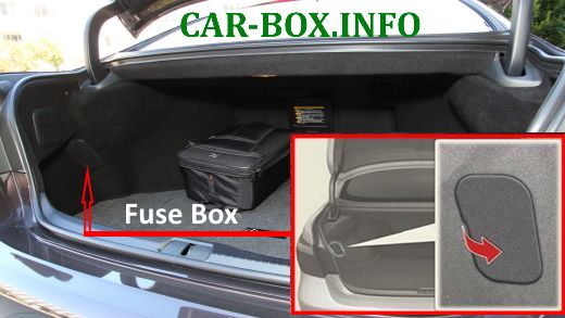
Located in the left side of the luggage compartment, under protective cover.

General view.
| Diagram | ||
|---|---|---|

|
||
| No. | Description | A |
| 1 | Audio system, rear passenger entertainment system, electric boot lid | 10 |
| 2 | Central locking, rear seat settings, interior lighting, siren, electric boot lid | 5 |
| 3 | - | 5 |
| 4 | - | - |
| 5 | Cooling fan | 20 |
| 6 | 5 | |
| 7 | Parking brake | 30 |
| 8 | Trunk lighting, seat belt lighting | 5 |
| 9 | ABS system, condenser | 10 |
| 8 | Stop lamps, reversing lamps | 5 |
| 10 | ||
| 11 | Stop lamps, additional brake light | 10 |
| 12 | - | - |
| 13 | Tail light, license plate light | 5 |
| 14 | Heated and ventilated seats | 10 |
| 15 | Rear seat settings | 10 |
| 16 | Central locking, refrigerator, air conditioning | 10 |
| 17 | Condenser, brake system, rear seat settings | 5 |
| 18 | Audio system, rear passenger entertainment system | 5 |
| 19 | Rear cigarette lighter fuse Lexus LS 460 | 15 |
| 20 | Socket | 15 |
| 21 | Rear seat settings | 30 |
| 22 | Shoulder anchor | 10 |
| 23 | Rear curtain | 10 |
| 24 | Preventive seat belts | 30 |
| 25 | Trunk lid drive | 30 |
| 26 | Fuel tank hatch, electric boot lid | 15 |
| 27 | No | - |
