In this article, we will take a detailed look at the fuse diagrams for the Lincoln Aviator (first generation; UN152): 2002, 2003, 2004, 2005 release.

Fuses #3 (2005 only), #16 (Power outlet 3), #25 (Power outlet 1) and #28 (Power outlet 2) in the engine bay block and fuse #16 (2003-2004 only) in the passenger compartment block are resposible for the cigarette lighter.
In the engine compartment
Location of the components:
- Fuse block;
- Relay block.
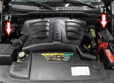
Fuse box
Located in the left side of the engine area, behind the plastic cover.
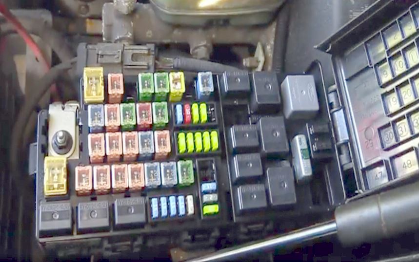
Access example.
| Diagram | ||
|---|---|---|

|
||
| No. | Description | Amps |
| Relay | ||
| 47 | Horn | |
| 48 | Fuel pump relay | |
| 49 | High beam headlamp | |
| 50 | Fog lamp | |
| 51 | Empty | |
| 52 | A/C clutch relay | |
| 53 | Trailer tow right turn | |
| 54 | Trailer tow left turn | |
| 55 | Blower motor | |
| 56 | Starter relay | |
| 57 | PTEC | |
| 58 | Ignition relay | |
| 59 | 2003-2004: Driver brake applied relay | |
| Diode | ||
| 60 | PCM | |
| 61 | A/C clutch | |
| Fuses | ||
| 1 | Power Junction Box (PJB) | 60 A |
| 2 | Door locks (BSM) | 30 A |
| 3 | Cigarette lighter fuse (2005) | 20 A |
| 4 | Heated backlight/mirrors | 40 A |
| 5 | ABS / Roll Stability Control (RSC) pump | 40 A |
| 6 | Delayed accessory | 60 A |
| 7 | Daytime Running Lamps (DRL) | 20 A |
| 8 | Cooling fan | 20 A |
| 9 | Headlamp switch | 20 A |
| 10 | ABS module / RSC module (valves) | 30 A |
| 11 | PTEC relay contacts | 40 A |
| 12 | Ignition/Starter relay | 50 A |
| 13 | Trailer tow relays | 40 A |
| 14 | Brake lamp feed | 15 A |
| 15 | Courtesy lights (2005) / Keep alive power (PTEC/cluster/DEATC) | 10 A |
| 16 | 12V Power outlet #3 | 20 A |
| 17 | Rear wiper | 20 A |
| 18 | 4x4 module | 20 A |
| 19 | Driver window motor | 30 A |
| 20 | Electric trailer brake module | 30 A |
| 21 | Memory seat module | 30 A |
| 22 | Exterior lamps (low beam headlamps, fog lamps, high beam headlamps) | 20 A |
| 23 | Ignition switch | 30 A |
| 24 | Horn relay | 20 A |
| 25 | 12V Power outlet #1 | 20 A |
| 26 | Fuel pump relay contacts | 20 A |
| 27 | Trailer tow relays | 20 A |
| 28 | 12V Power outlet #2 | 20 A |
| 29 | Power Junction Box (PJB) | 60 A |
| 30 | Front wiper | 30 A |
| 31 | Climate-controlled seats modules | 30 A |
| 32 | Passenger seat switch | 30 A |
| 33 | Auxiliary blower motor | 30 A |
| 34 | HID relay - Right | 20 A |
| 35 | HID relay - Left | 20 A |
| 36 | Blower motor | 40 A |
| 37 | A/C clutch relay, Transmission, TXV, Speed control | 15 A |
| 38 | HEGO, Canister vent, VMV, EGR module, IMCC-LSRC, Heated PCV (2003) | 15 A |
| 39 | Idle air control (2005) / Injectors | 15 A |
| 40 | PTEC, Fuel pump relay, Mass Air Flow (MAF) sensor | 15 A |
| 41 | PTEC diode/relay / Coil on plug | 25 A |
| 42 | Halogen: Headlamp Right low beam | 10 A |
| 43 | Halogen: Headlamp Left low beam | 10 A |
| 44 | 2004-2005: Heated PCV valve (only w/DRL) | 2 A |
| 2003: Fog lamps | 15 A | |
| 45 | 2003-2004: Brake Pressure Switch | 2 A |
| 46 | Headlamp High beams, Fog lamps (2004-2005) | 20 A |
| 62 | Circuit Breaker: Moonroof, Power windows, Audio (delayed accessory) | 30 A |
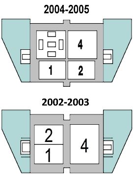
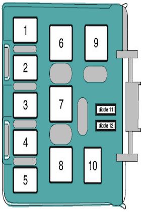
Relay block
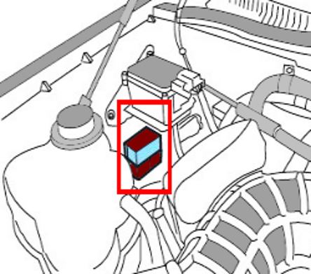
Located on the front fender well (underneath the speed control unit).
|
|
| 1 | HID relay - Left |
| 2 | HID relay - Right |
| 4 | EDF (low speed fan) relay |
In the passenger compartment
There are two blocks here: the main fuse box is located in front under the instrument panel, the additional relay box is located in the rear of the cabin.
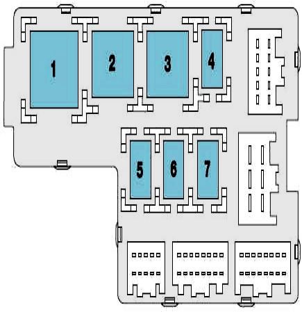
Front fuse block
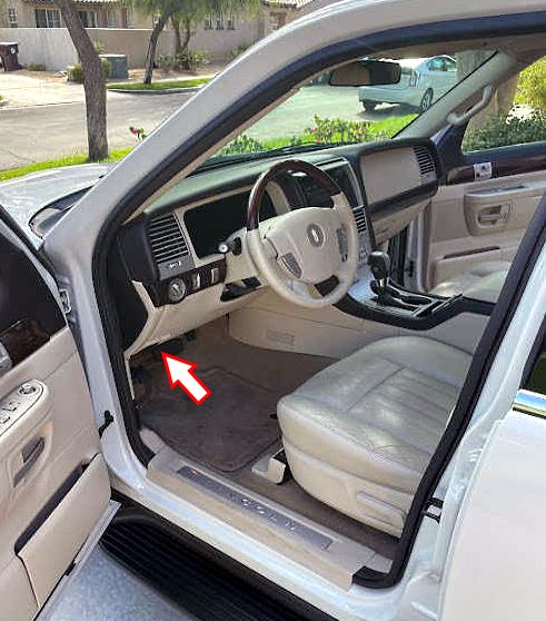
Located on the driver’s side below the dashboard.
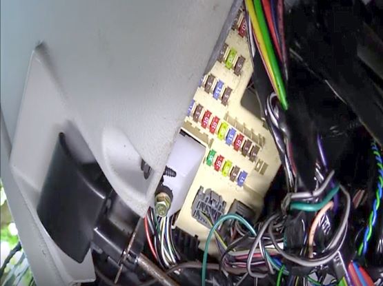
Access example.
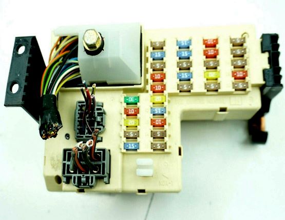
General view of the fuse box.
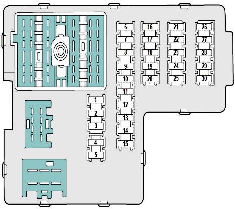
| Diagram | ||
|---|---|---|
| No. | Description | Amps |
| Front Side | ||
|
||
| 1 | Driver seat switch, Sunroof, Driver seat lumbar | 30 A |
| 2 | VAPS module, Body security module, Memory seat module, Tire Pressure Monitor System (TPMS), Sunload/Autolamp sensor, SecuriLock LED | 10 A |
| 3 | Navigation module / Radio | 20 A |
| 4 | Front wiper | 5 A |
| 5 | Turn/hazards: Flasher | 15 A |
| 6 | Electronic Hidden Antenna Module (EHAM) (antenna amp), Radio, Sunroof, Driver power window motor, Navigation contol unit and microphone | 5 A |
| 7 | DEATC module / Heated mirrors | 15 A |
| 8 |
|
5 A |
| 9 |
|
10 A |
| 10 | Heated backlight relay coil, Auxiliary A/C temperature blend/mode actuator, Climate seat modules, A/C clutch relay contact | 10 A |
| 11 | Empty | 20 A |
| 12 | Restraints module | 15 A |
| 13 | Brake shift interlock | 10 A |
| 14 | 2002-2003: Cornering lamps | 5 A |
| 15 | Rear wiper module, Instrument cluster, Tire Pressure Monitor System (TPMS) | 5 A |
| 16 | 2002-2003: Cigarette lighter, OBD II, Liftgate release relay coil and contacts | 15 A |
| 2005: OBD II port | ||
| 2004: Cigarette lighter fuse, OBD II | 20 A | |
| 17 | Battery saver relay coil and contact / Delayed accessory relay coil | 15 A |
| 18 | Empty | 5 A |
| 19 | Washer pump | 15 A |
| 20 | Shifter, Power mirror switch, Clock, DVD system | 5 A |
| 21 |
|
10 A |
| 22 | ABS/RSC control unit | 10 A |
| 23 | 2004-2005: Liftgate release relay coil and contact | 7,5 A |
| 2002-2003: Autolamp sensor / Sunload | 5 A | |
| 24 | 2004-2005: Navigation / Subwoofer | 30 A |
| 2002-2003: Navigation / Subwoofer | 20 A | |
| 25 | Trailer tow battery charge relay coil, Puddle lamp relay coil (2002-2003) | 5 A |
| 26 | Empty | 5 A |
| 27 | VAPS module / Rear park assist | 5 A |
| 28 | Navigation / Radio module | 5 A |
| 29 | DTRS, Fuse #28 | 10 A |
| 30 | Compass module, Instrument cluster, Auxiliary A/C relay coil | 5 A |
| Rear Side To access, remove the fuse box |
||
|
||
| 1 | Flasher (turn/hazard) relay | |
| 2 | Heated backlight | |
| 3 | Delayed accessory | |
| 4 | Empty | |
| 5 | Battery saver | |
| 6 | Empty | |
| 7 | Empty | |
Rear relay block
Located on the rear quarter trim panel.
For service of the block contact authorized service center or dealer.
| Diagram | |
|---|---|
|
|
| No. | Description |
| 1 | Liftgate release solenoid |
| 2 | Empty |
| 3 | Empty |
| 4 | Trailer tow back-up lamps |
| 5 | Empty |
| 6 | Empty |
| 7 | Trailer tow battery charge |
| 8 | Trailer tow park lamps |
| 9 | Empty |
| 10 | 2002-2003: Puddle lamps |
| 11 | Empty |
| 12 | Empty |
