Mazda BT-50 is a mid-size pickup truck of the Japanese company. It is produced since 2006, replacing the B-Series pickup trucks. In this article, we will take a detailed look at the fuse box diagrams for the Mazda BT-50 (codename J97M) 2006, 2007, 2008, 2009, 2010, 2011, 2012 years of manufacture.

Here you will find the locations and photos of distribution boxes. The fuses responsible for the “Cigarette lighter” and “Fuel Pump” are highlighted in bold.
In the passenger compartment
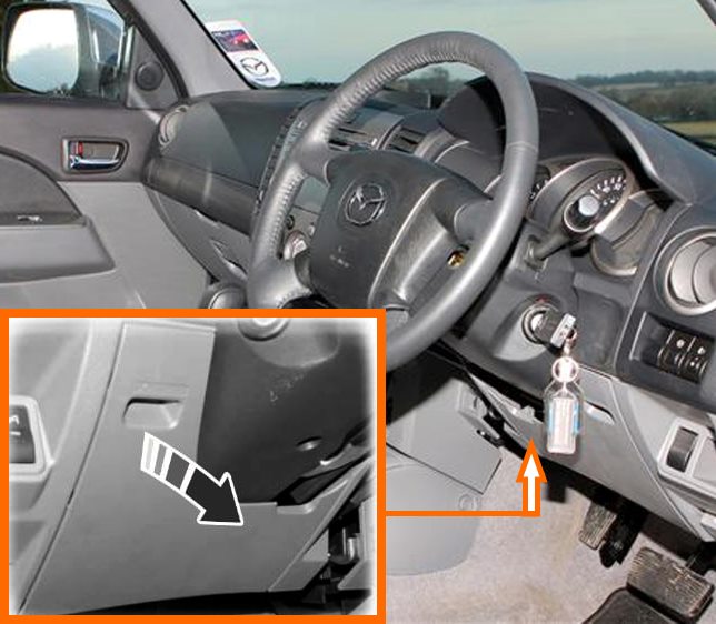
The distribution box is located under the dashboard behind a plastic cover.
General view of the Mazda BT50 interior fuse box.
| Diagram | ||
|---|---|---|
|
||
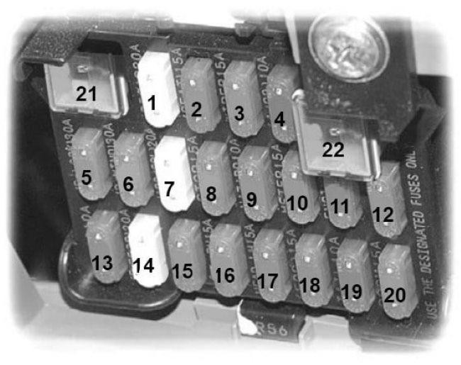
| No. | Description | Amps |
| 1 | Mazda bt 50 cigarette lighter fuse, audio system, electrically operated exterior mirrors, additional electrical outlet | 20 |
| 2 | Heated seat | 15 |
| 3 | Windshield wipers and washers | 15 |
| 4 | Air conditioning and ABS relay | 10 |
| 5 | Central locking system | 30 |
| 6 | Power windows | 30 |
| 7 | ABS solenoid valve | 20 |
| 8 | Brake lights and horn | 15 |
| 9 | Emergency light signalling | 10 |
| 10 | Instrument cluster, reversing lights, direction indicators and automatic front wheel hub locking system (RWF) | 15 |
| 11 | Engine management systems | 15 |
| 12 | Cruise control | 5 |
| 13 | Electromagnetic clutch of the air conditioning system | 10 |
| 14 | Rear window heater | 20 |
| 15 | Rear fog light | 10 |
| 16 | Right headlight | 15 |
| 17 | Left headlight | 15 |
| 18 | Front fog lights | 15 |
| 19 | Rear position lamps, front position lamps, number plate illumination lamp | 10 |
| 20 | Interior lighting and indicator lamps | 15 |
| 21 | Spare | |
| 22 | Power windows | 30 |
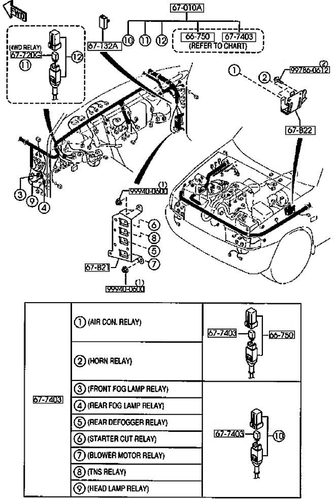
| General layout of the relay modules |
|---|
|
| 1. AIR CON RELAY - air conditioning 2. HORN RELAY - beep 3. FRONT FOG LAMP RELAY - front fog lamps 4. REAR FOG LAMP RELAY - rear fog lamps 5. REAR DEFOGGER RELAY - rear window heater 6. STARTER RELAY - starter 7. BLOWER MOTOR RELAY - Fan Motor Relay 8. TNS RELAY - parking lights 9. HEAD LAMP RELAY - front headlights |
In the engine compartment
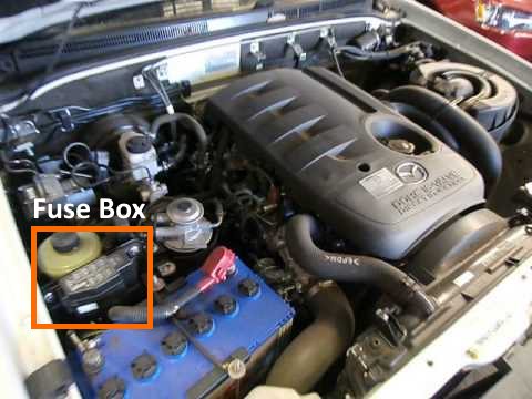
The distribution box is located next to the battery, behind the protective cover.
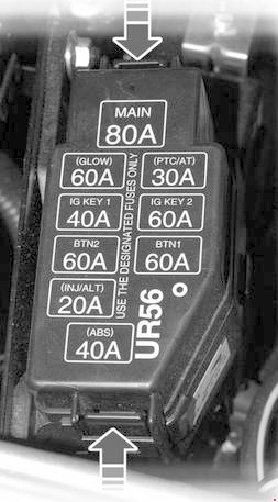
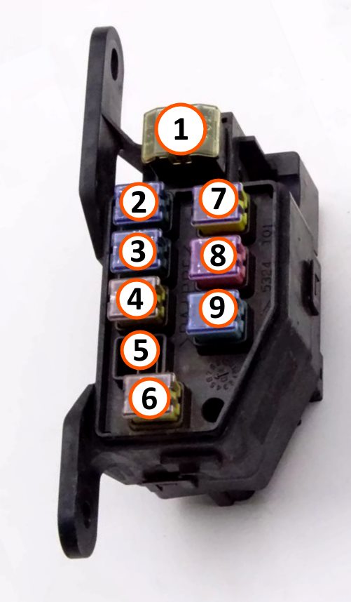
Example of a schematic from the block cover.
| Diagram | ||
|---|---|---|
|
||
| No. | Decoding | Amps |
| 1 | MAIN - To protect all circuits | 80 |
| 2 | GLOW - Glow plugs | 60 |
| 3 | IG KEY 1 - Engine management systems, instrument cluster, power outlets and power windows | 40 |
| 4 | BTN - Backlight HEAD - Headlights | 60 |
| 5 | INJ/ALT - Injectors and fuel system | 20 |
| 6 | ABS - ABS system electric motor, hazard warning lights, brake lights | 40 |
| 7 | PTC - Fuel heater, additional heater | 30 |
| 8 | IG KEY 2 - Air conditioning system, windshield wipers and washers | 60 |
| 9 | BTN 1 - Air conditioning system, heated rear window or Central locking system or ABS solenoid valve 1, or power windows or tail light or fog light bulbs | 60 |
