
Most power supply circuits in these Japanese trucks are protected by fuses. High-draw electrical consumers are connected via relays. Protective components are installed in power distribution boxes located on the frame chassis and in the cab.

These fuse diagrams apply to 1989, 1990, 1991, 1992, 1993, 1994, 1995, 1996, 1997, 1998, 1999, and 2000 model year Mazda Titan (Fifth generation) trucks equipped with diesel engines: Mazda XA (2.5 L), HA (3.0 L), VS (3.0 L), SL (3.5 L), SL Turbo (3.5 L), TF (4.0 L), and Isuzu 4HF1 (4.3 L), 4HG1 (4.6 L).

The main fuse block is located behind the instrument panel, and the auxiliary block is mounted on the frame chassis next to the battery.
Chassis Fuse Box

The power distribution box is located on the frame chassis near the battery.
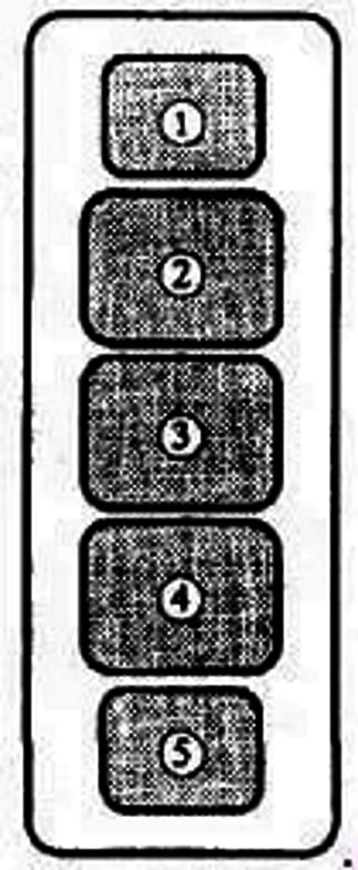
Legend:
- Ignition switch / Alternator – 80 A
- Glow plugs / Ignition switch / Alternator – 100 A
- Main power circuit protection – 60 A
- Headlamps – 30 A
- Cargo lamp – 30 A
Relay Modules

Relay module layout: 1 – Stop lamp check relay, 2 – Turn signal flasher relay, 3 – Horn relay, 4 – Fast idle warm-up relay, 5 – Intake air heater relay, 6 – Auxiliary relay, 7 – Glow plug relay, 8 – Intermittent windshield wiper relay.
Passenger Compartment (Cab)

Located inside the instrument panel. Access the panel by removing the protective cover.
Type 1
First-generation fuse block configuration.
| Diagram | ||
|---|---|---|

|
||
| No. | Rating (A) | Protected Circuit |
| A | 15 | Radio, clock, cigarette lighter |
| B | 10 | Fog lamps |
| C | 10 | Parking / position lamps |
| D | 10 | Auxiliary / optional equipment |
| E | 20 | Central door locking |
| F | 15 | Stop lamps, horn |
| G | 10 | Hazard warning flashers |
| H | 10 | Dome light, clock, audio system |
| I | 20 | Heater blower motor |
| J | - | Spare |
| K | 15 | Windshield wiper and washer |
| L | - | Spare |
| M | - | Spare |
| N | 10 | Turn signal indicators |
| O | 10 | Instrument cluster |
| P | 15 | Radiator cooling fan |
| Q | - | Auxiliary / optional equipment |
| R | - | |
| S | 15 | |
| T | - | Heater |
| U | 30 | Power windows |
| V | 30 | Heater |
Type 2
Second-generation fuse block configuration.

Access panel location.
| Diagram | ||
|---|---|---|

|
||
| Code | Protected Circuit | Rating (A) |
| WIPER | Windshield wiper and washer system | 15 |
| HEATER | Heater / HVAC system | 30 |
| ROOM | Dome light, interior lamps, radio | 10 |
| ENGINE | Starting system / Ignition switch | 15 |
| METER | Tail lamps, instrument cluster, brake light switch, fuel shut-off solenoid, fast-idle warm-up system | 15 |
| TURN | Turn signal indicators | 15 |
| TAIL | Parking lamps, license plate lamp, combination lamps | 15 |
| STOP | Stop lamps, horn | 15 |
| HAZARD | Hazard warning flashers | 15 |
| CIGAR | Cigarette lighter, audio system | 15 |
