The CLS made its debut at the New York Auto Show in 2004. The car is positioned as a four-door coupe, but in fact it is a fastback sedan with rear-wheel drive layout. The car was designed by American designer Michael Fink. In this article we will understand in detail fuse box diagrams Mercedes C219 CLS class (first generation; modifications: CLS280, CLS300, CLS320, CLS350, CLS500, CLS55) 2004, 2005, 2006, 2007, 2008, 2009, 2010 years of manufacture.

Here you will find the locations and photos of the mounting blocks. Also, we will separately mark the fuses responsible for the cigarette lighter and the fuel pump.
In the trunk
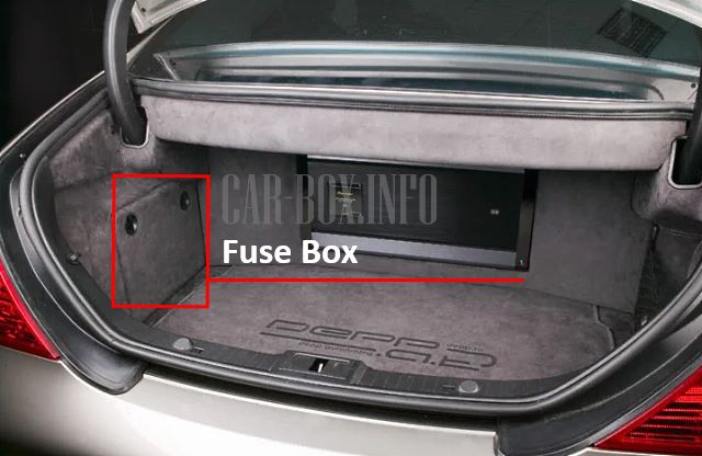
Located on the left side behind the trim.

Photo is an example.
| Diagram | ||
|---|---|---|

|
||
| No. | Relay assignment | |
| A | petrol fuel pump relay (except 113.990 (CLS 55 AMG), 156.983 (CLS 63 AMG), 272.985) | |
| supercharger air cooler circulation pump (113.990 (CLS 55AMG)) | ||
| B | Relay 2, terminal 15R | |
| C | Spare | |
| D | Spare | |
| E | Rear window heater relay | |
| F | Relay 1, terminal 15R | |
| G | 1 filler cap polarity switch | |
| I | 2 filler cap polarity switch | |
| No. | A | Purpose of fuses |
| 1 | 30 | Front passenger's partial position adjustment switch |
| Driver's seat partial adjustment switch (from 2007) | ||
| Driver's side front seat position adjustment control unit, with memory | ||
| 2 | 30 | Partial electric driver's seat adjustment switch |
| Front seat adjustment control unit, passenger side | ||
| 3 | 7.5 | TPM control unit [RDK] (tire pressure sensor) |
| PTS (parktronic) | ||
| Navigation processor | ||
| Combo TV tuner (analog / digital) | ||
| 4 | 20 | Except for the 156.983 (CLS 55 AMG) and the 272.985 motor: gasoline pump / via fuel pump relay. |
| 4 | 7.5 | Engine 113.990 (CLS 55 AMG): Charge air cooler circulation pump |
| 5 | - | Spare relay 2 |
| 6 | 40 | Audio gateway control unit |
| 7 | 15 | Rear wiper relay |
| 8 | 7.5 | Left antenna amplifier module |
| Horn (beep) | ||
| signal with additional battery | ||
| ATA Tilt Sensor [EDW] | ||
| 9 | 25 | Ceiling panel control unit |
| 10 | 40 | Rear window heating |
| 11 | 20 | - |
| 12 | 15 | USA: luggage compartment socket |
| 13 | 15 | Internal socket |
| 14 | 5 | - |
| 15 | 10 | gas tank hatch CL [ZV] |
| 16 | 20 | HS [SIH] and seat ventilation control unit |
| 17 | 20 | - |
| 18 | 20 | - |
| 19 | 20 | Pneumatic pump with multi-circuit seat |
| 20 | 7.5 | Rear window curtain relay |
In the passenger compartment
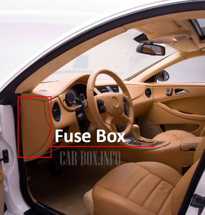
The mounting block is located on the driver's side at the end of the instrument panel behind the protective cover.
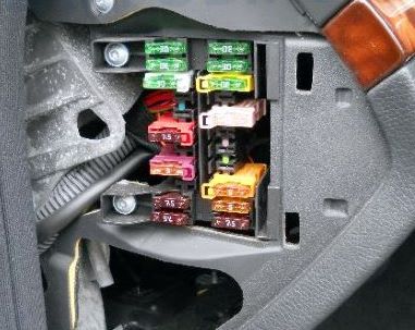
Access example.
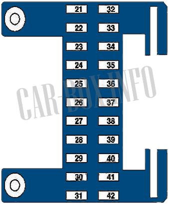
| Diagram | ||
|---|---|---|
|
||
| No. | A | Decryption |
| 21 | 30 | Rear Right Door Control Module |
| 22 | 30 | Front Right Door Control Module |
| 23 | 30 | Passenger side front seat adjustment control module with memory |
| 24 | 25 | Rear Module / Keyless Go |
| Rear Left Door / Keyless Go | ||
| Rear Right Door / Keyless Go | ||
| 25 | 20 | Stationary heater (STN) |
| 25 | 5 | Additional fuse via multi-position fuse for stationary heater: radio control receiver STH |
| 26 | 7.5 | CD changer |
| 27 | - | Spare |
| 28 | 15 | Radio |
| 28 | 5 | Radio remote control and navigation unit |
| Indication and control COMAND | ||
| 29 | 7.5 | Steering column module |
| rotary switch | ||
| EIS [EZS] | ||
| 30 | 7.5 | Data Link Connector |
| 31 | 5 | Top control panel control unit |
| Disconnection relay for disconnected loads (before 2007) | ||
| 32 | 30 | Rear left door control unit |
| 33 | 30 | Front left door control unit |
| 34 | 30 | Driver's side front seat adjustment control unit, with memory |
| 35 | 5 | Control unit WSS (Weight Sensing System) |
| 36 | 25 | HS [SIH] and seat ventilation control unit |
| Right SAM control unit | ||
| 37 | 15 | AIRmatic with ADS control unit |
| 38 | 7.5 | NECK-PRO headrest relay |
| 39 | 5 | Lower control panel of the control unit |
| 40 | 10 | HS [SIH] and seat ventilation control unit |
| 41 | 5 | Central gateway control unit |
| 42 | 7.5 | ME-SFI [ME] block |
| Driver side SAM with fuse and relay module | ||
In the engine compartment
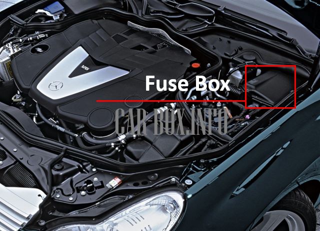
Located on the left side of the engine compartment behind the cover.
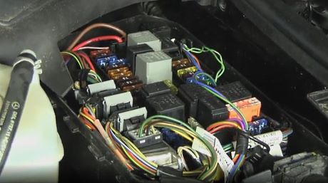
Example of access to the fuse box.
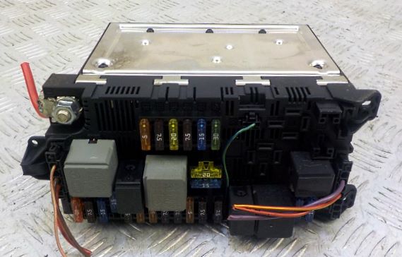
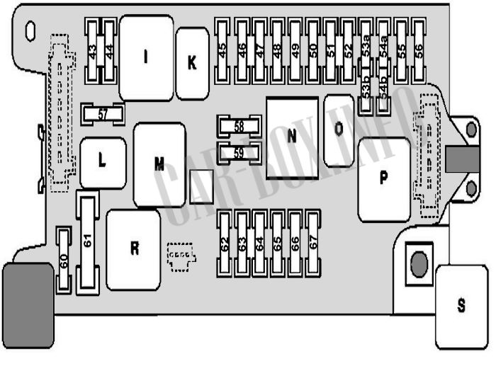
General view.
| Diagram | ||
|---|---|---|
|
||
| No. | A | Description |
| I | - | Terminal 87 relay, motor |
| K | - | Terminal 87 relay, chassis |
| L | - | Starter relay |
| M | - | Reserve |
| N | - | Terminal 15 relay |
| O | - | Fanfare horn relay |
| P | - | Relay terminal 15R |
| R | - | Air pump relay (except engine 113.990 (CLS 55 AMG) and 156.983 (CLS 63 AMG)) |
| - | Oil cooler fan relay (engine 113.990 (CLS 55 AMG) and 156.983 (CLS 63 AMG) only) | |
| S | - | Relay AIRmatic (semi-active air suspension) |
| 43 | 15 | Engine M156, M272, M273: ME-SFI [ME] module / Rear SAM control unit |
| M642 engine: CDI control unit / Rear SAM control unit | ||
| Engine M113: ME-SFI [ME / Rear SAM control unit / Fuel pump and air injection relay | ||
| 44 | 15 | M642 motor: CDI unit |
| 45 | 7.5 | AIRmatic with ADS control unit |
| 46 | 7.5 | Automatic 5-speed transmission (NAG): ETC [EGS] |
| 7-speed automatic transmission: Electric controller unit (VGS) | ||
| 47 | 5 | ESP system |
| 48 | 7.5 | Restraint systems control unit |
| 49 | 7.5 | Reversible front retractor with emergency tension front left (from 2007) |
| Reversible front retractor with reverse tension right (from 2007) | ||
| Restraint systems control unit (up to 2007) | ||
| Front passenger seat occupancy sensor and child seat detection sensor (up to 2007) Head restraints NECK-PRO relay (2006) | ||
| 50 | 5 | VICS Power Supply Disconnect Point |
| 51 | 5 | - |
| 52 | 7.5 | Glovebox illumination with switch |
| Instrument cluster | ||
| Rotary light switch | ||
| Bi-Xenon headlamps: Headlamp angle corrector control unit | ||
| 53a | 15 | Horn (beep) relay |
| 53b | 15 | |
| 54a | 15 | Cigarette lighter fuse Mercedes CLS 219 |
| 54b | 15 | |
| 55 | 7.5 | VICS Power Supply Disconnect Point |
| 56 | 40 | Wiper motor |
| 57 | 25 | Motor M156, M272, M273: Module ME-SFI [ME] / Rear control unit SAM |
| M642 engine: CDI / Rear SAM control unit | ||
| 58 | 15 | Purge Control Valve (up to 2007) |
| Engine 272: AAC with integrated auxiliary fan motor controller (up to 2007) | ||
| USA - Activated carbon filter shut-off valve (up to 2007) | ||
| Engine 642: CDI Block (2006) | ||
| Engine M113, M156, M272, M273: Cylinders ignition coil | ||
| Valid for engine M113: Left and right O2 sensor after TWC [KAT] | ||
| 59 | 15 | Starter relay |
| 60 | 10 | Engine 113.990 (CLS 55 AMG), 156.983 (CLS 63 AMG): Oil cooler fan |
| 61 | 40 | Electric air pump |
| 62 | 30 | Back-up relay |
| 63 | 15 | - |
| 64 | 7.5 | Rotary light switch |
| Comfort control and control unit for the automatic air conditioning system | ||
| Instrument cluster (up to 2007) | ||
| AAC Control and Control Unit [KLA] (up to 2007) | ||
| 65 | 20 | EIS unit [EZS] |
| electric steering lock | ||
| 66 | 7.5 | Left hand drive: Front right headlight |
| Right hand drive: front left headlight | ||
| Bi-xenon headlight: HRA power supply. | ||
| 67 | 10 | Stop lamp switch |
