The Gelandewagen or Mercedes-Benz G-Class is a legendary SUV produced at the Steyr-Puch (now Magna Steyr) factory in Austria. It was developed as a military vehicle, and a civilian version was offered in 1979. This is one of the few models, which are equipped with three fully lockable differentials. In this article, we will take a detailed look at the fuse box diagrams for the Mercedes W463 Gelendwagen (2nd Gen; G-class) 1989, 1990, 1991, 1991, 1992, 1993, 1994, 1995, 1996, 1997, including restyling 1998, 1999, 2000, 2001, 2002, 2003, 2004, 2005, 2006 years of manufacture..

Here you will find the locations and photos of distribution boxes. The fuses responsible for the “Cigarette lighter” and “Fuel Pump” are highlighted in bold.
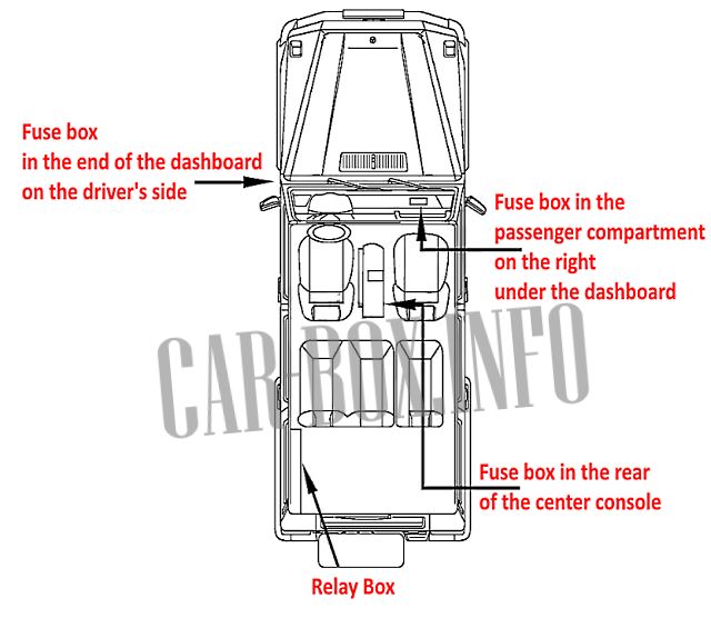
General layout of the distribution boxes.
In the passenger compartment
There are three distribution boxes here, which are responsible for protecting the vehicle's electrical circuits.
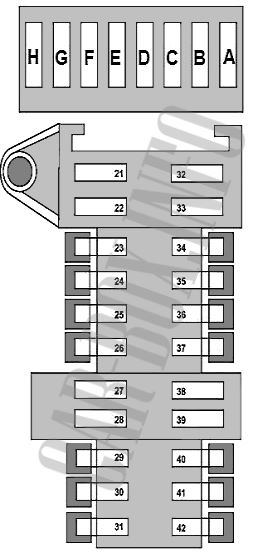
Block No. 1
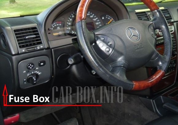
The first distribution box is located on the driver's side at the end of the dashboard, behind the plastic cover.

General view of the top board.
| Diagram | ||
|---|---|---|
|
||
| No. | A | Description |
| A | 15 | Spare |
| B | 10 | ABS control unit pin 87 |
| C | Reserve | |
| D | 5 | Optional equipment switch, brake light switch |
| E | Reserve | |
| F | 20 | Heated rear seat |
| G | 20 | Condenser fan |
| H | 30 | |
| 21 | 30 | Front left door control unit |
| 22 | 30 | Front right door control unit |
| 23 | 5 | Rear lamp for local lighting |
| 24 | 20 | Brush defroster |
| 25 | 10 | Heated driver's seat |
| 26 | 7.5 | Voltage transformer |
| 27 | 30 | Driver's seat position adjustment electric actuator control unit |
| 28 | 30 | Optional equipment connector |
| 29 | Reserve | |
| 30 | 40 | Air conditioning |
| 31 | 20 | Electronic ignition lock |
| 32 | 30 | Rear left door control unit |
| 33 | 30 | Rear right door control unit |
| 34 | 7.5 | Cellular telephone system |
| 35 | 30 | Heater |
| 36 | 15 | spare |
| 37 | 30 | Vacuum pump (differential lock actuator) |
| 38 | 40 | Power passenger seat |
| 39 | 7.5 | Transfer case control unit |
| 40 | Reserve | |
| 41 | 7.5 | Air conditioning |
| 42 | 15 | Instrument panel |
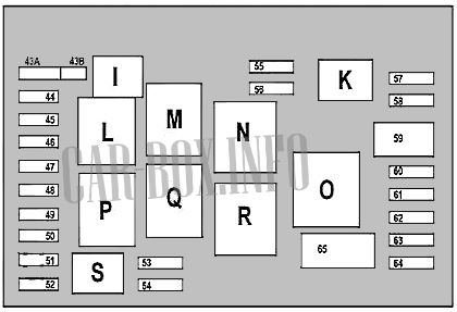
Block No. 2
The second interior fuse box is located on the passenger side under the instrument panel.

The photo shows an example.
| Diagram | ||
|---|---|---|
|
||
| No. | Relay | |
| I | Horn (beep) relay | |
| K | Circuit 87 | |
| L | wiper control relay (operating speed) | |
| M | Circuit 15R | |
| N | Circuit 15 | |
| O | air pump | |
| P | Circuit 15 | |
| Q | wiper switch | |
| R | Circuit 87 | |
| S | starter | |
| No. | A | Circuit breakers |
| 43a | 15 | Horn (beep) |
| 43b | 15 | |
| 44 | 5 | Cellular telephony |
| 45 | 10 | Safety Airbag |
| 46 | 20 | Wiper |
| 47 | 15 | Lighting, Mercedes Gelandewagen W463 cigarette lighter fuse |
| 48 | 15 | Ignition coil |
| 49 | 10 | Safety Airbag |
| 50 | 5 | Reserve |
| 51 | 7.5 | Air conditioning, automatic transmission control unit |
| 52 | 15 | Starter |
| 53 | 15 | Cooling fan |
| 54 | 15 | Heater fan |
| 55 | 7.5 | Automatic transmission control unit |
| 56 | 7.5 | Automatic transmission selector controller |
| 57 | 5 | Electronic ignition lock |
| 58 | 40 | Fuse box (8 pcs.) |
| 59 | 50 | ABS return pump |
| 60 | 40 | ABS modulator |
| 61 | 15 | Reserve |
| 62 | 5 | LDS system |
| 63 | 5 | Reserve |
| 64 | ten | Audio system |
| 65 | 40 | Secondary air pump |
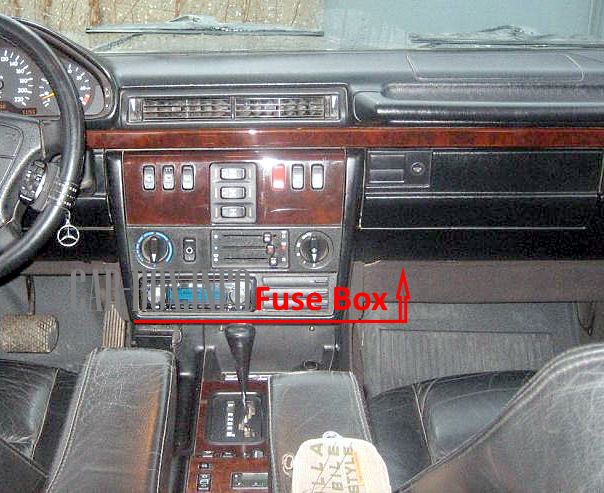
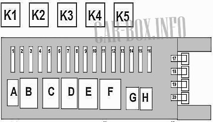
Block No. 3
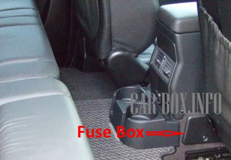
The third unit is located at the rear of the console. Unscrew the fixing screws (1) and remove the cover (2).
| Diagram | ||
|---|---|---|
|
||
| No. | Relay | |
| A | Fuel pump relay mercedes w463 | |
| B | relay 2 circuit 15R | |
| C | spare | |
| D | ||
| E | Heated rear window | |
| F | relay 1 circuit 15R | |
| G | 1/2 fuel filler flap actuator | |
| H | ||
| K1 | Stop lights | |
| K2 | Fuel pump relay | |
| K3 | ABS system | |
| K4 | Starter, cooling fan | |
| K5 | relay circuit 15R | |
| No. | A | Circuit breakers |
| 1 | 30 | Circuit connector 15R |
| 2 | 30 | |
| 3 | 5 | TV - receiver |
| 4 | 15 | Fuel module (Gelandewagen fule pump fuse) |
| 5 | 20 | spare |
| 6 | 20 | |
| 7 | 20 | |
| 8 | 7.5 | Antenna, anti-theft siren, tilt sensor |
| 9 | 25 | Upper ceiling control panel |
| 10 | 20 | Rear window heater |
| 11 | 20 | spare |
| 12 | 15 | |
| 13 | 20 | Bypass pump outlet 15 |
| 14 | 15 | Rear wiper |
| 15 | 10 | Fuel filler flap actuator |
| 16 | 5 | Voice control system |
| 17 | 20 | Trailer electrical circuit connection determination unit |
| 18 | 20 | Trailer circuit connector |
| 19 | 20 | Relief pump outlet 30 |
| 20 | 10 | Rear door lock actuator |
In the trunk
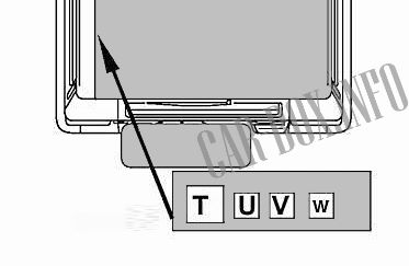
The relay panel is located on the left side behind the trim.
| Diagram | |
|---|---|
| No. | Appointment |
| V | rear wiper |
| W | |
| T | central locking system |
| U | power supply circuit of the automatic transmission output shaft speed sensor |

Very Nice website God Bless you all