
The first-generation Mercedes-Benz M-Class was produced from 1997 through 2005. This midsize body-on-frame SUV was offered in five-seat or seven-seat configurations. It was the first luxury SUV to feature an Electronic Stability Program (ESP). In this guide, we provide detailed fuse box diagrams and relay layouts for the Mercedes-Benz W163 (1st-Gen M-Class: ML230, ML320, ML350, ML430, ML500) across model years 1997 to 2005.

Below you will find the locations, diagrams, and photos for the electrical distribution boxes. Fuses for critical components such as the “Cigarette Lighter” and “Fuel Pump” are highlighted in bold.
Passenger Compartment Fuse Box
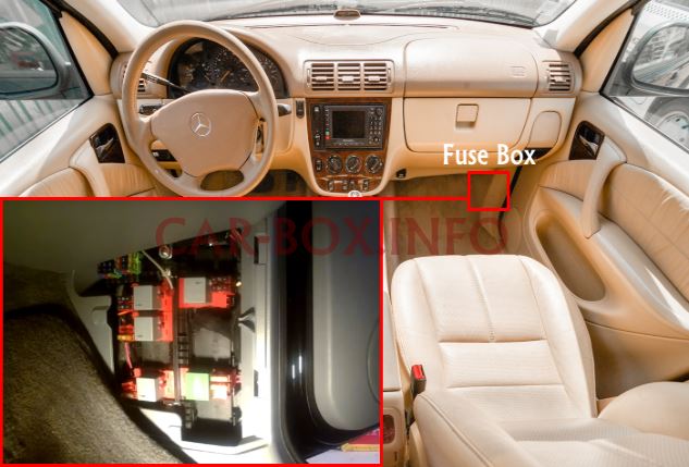
The fuse box is located in the front passenger footwell, behind the trim panel near the door pillar. The internal panel layout varies depending on the model year.
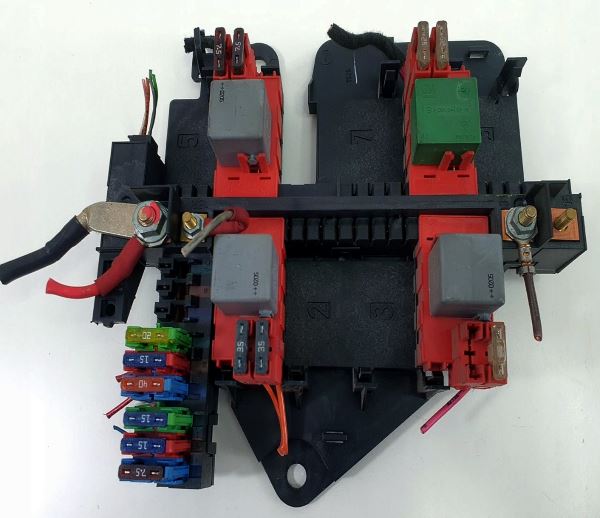
General view of the Mercedes-Benz M-Class (W163) interior fuse box.
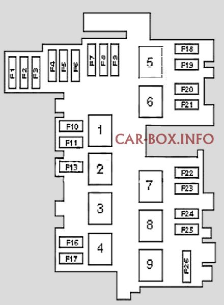
| Diagram | ||
|---|---|---|
|
||
| Vehicles up to VIN A289564 / X754619 | ||
| No. | Protected Circuit / Component | Rating (A) |
| F1 | Passenger airbag deactivation indicator lamp | 7.5 |
| F2 | Cigarette lighter | 20 |
| F3 | Rear window wiper motor | 15 |
| F4 | - | |
| F5 | Instrument cluster, A/C system control unit | 7.5 |
| F6 | Auxiliary power socket (12V) | 20 |
| F7 | - | |
| F8 | Heated front seats | 20 |
| F9 | - | |
| F10 | Driver seat power adjustment switch module | 30 |
| F11 | Passenger seat power adjustment switch module | 30 |
| F13 | Fuel pump / fuel level sensor | 20 |
| F16 | - | |
| F17 | Heated rear window (defogger) | 25 |
| F18 | - | |
| F19 | Headlamp washer pump | 30 |
| F20-25 | ||
| F26 | Main ignition circuit relay | 70 |
| No. | Relay Component | |
| 1 | Power seats | |
| 2 | Fuel pump relay | |
| 3 | ||
| 4 | Heated rear window (defogger) | |
| 5 | Headlamp washer pump | |
| 6-8 | ||
| 9 | Main ignition circuits | |
| Vehicles from VIN A289565 / X754620 | ||
| No. | Protected Circuit / Component | Rating (A) |
| F1 | Passenger airbag deactivation indicator lamp | 7.5 |
| F2 | Front cigarette lighter | 20 |
| F3 | Rear window wiper motor | 15 |
| F4 | Front HVAC / heater blower motor | 40 |
| F5 | Instrument cluster, A/C system control unit | 7.5 |
| F6 | Auxiliary power socket (12V) | 20 |
| F7-9 | - | |
| F10 | Driver seat power adjustment switch module | 35 |
| F11 | Passenger seat power adjustment switch module | 35 |
| F13 | Fuel pump / fuel level sensor | 20 |
| F16 | - | |
| F17 | Heated rear window (defogger) | 25 |
| F18 | - | |
| F19 | Headlamp washer pump | 30 |
| F20 | Right headlamp high beam | 7.5 |
| F21 | Left headlamp high beam, high-beam indicator light | 7.5 |
| F22 | - | |
| F23 | - | |
| F24 | Rear power windows | 25 |
| F25 | Front power windows | 25 |
| No. | Relay Component | |
| 1 | Power seats | |
| 2 | Fuel pump relay | |
| 3 | - | |
| 4 | Heated rear window (defogger) | |
| 5 | Headlamp washer pump | |
| 6 | High-beam headlamps | |
| 7 | - | |
| 8 | Main ignition circuits | |
| 9 | ||
Engine Compartment Fuse Box
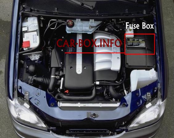
The fuse box is located on the left side of the engine compartment.
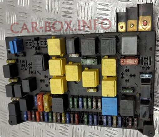
The photo above shows a typical arrangement.
| Diagram | ||
|---|---|---|
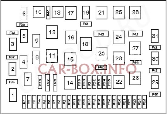
|
||
| Models produced up to 09/2001 | ||
| No. | Protected Circuit / Component | Rating (A) |
| F1 | Front auxiliary power socket (12V) | 15 |
| F2 | Left turn signals / direction indicators | 7.5 |
| F3 | Right headlamp high beam | 15 |
| F4 | Sunroof drive motor | 30 |
| F5 | Left headlamp high beam, high-beam indicator light | 7.5 |
| F6 | Rear window wiper motor | 7.5 |
| F7 | Windshield wiper/washer system, hazard warning switch | 15 |
| F8 | Transfer case control module (TCM) | 25 |
| F9 | License plate illumination lamps, switch lighting | 7.5 |
| F10 | Audio system, vanity mirror illumination, trip computer, glove box lamp, cigarette lighter (ML230, ML320, ML350, ML430, ML500), SRS indicator light, interior rearview mirror | 10 |
| F11 | Engine management system (gasoline engines) | 10 |
| F12 | Left front / left rear parking lamps | 7.5 |
| F13 | Interior lighting, trip computer, seat belt warning lamp, steering angle sensor, OBD-II diagnostic connector (DLC) | 10 |
| F14 | Engine management system (diesel engines) | 10 |
| F15 | Stop lamps (brake lights) | 10 |
| F16 | Diagnostic connector (DLC), reverse light switch, A/C control unit, fresh/recirculated air flap motor | 15 |
| F17 | Luggage compartment auxiliary power socket (12V) | 15 |
| F18 | Trailer tow wiring connector | 25 |
| F19 | Engine management system (gasoline engines) | 15 |
| F20 | Power exterior mirrors | 15 |
| F21 | Audio system | 25 |
| F22 | Automatic transmission, transfer case control module, traction control system (ETS/ESP), cruise control, steering angle sensor | 15 |
| F23 | - | |
| F24 | Right front / right rear parking lamps | 7.5 |
| F25 | Right turn signals / direction indicators | 7.5 |
| F26 | Engine management system (gasoline engines) | 15 |
| F27 | Traction Control System (ETS/ESP) | 40 |
| F28 | Heated seats | 20 |
| F29 | Multifunction switch / power window switch module | 30 |
| F30 | 30 | |
| F31 | Power sunroof switch, power exterior mirrors, rear power windows | 15 |
| F32 | Front right power seat | 30 |
| F33 | Front left power seat | 30 |
| F34 | Left headlamp low beam, headlamp leveling motor | 7.5 |
| F35 | Right headlamp low beam | 7.5 |
| F36 | Heated rear window (defogger) | 25 |
| F37 | Horn | 20 |
| F38 | Fuel pump module / fuel level sensor | 20 |
| F39 | - | |
| F40 | Brake booster vacuum pump (ML 270 CDI) | 25 |
| F41 | Auxiliary coolant pump motor, fuse/relay box cooling fan motor | 25 |
| F42 | Central locking system | 20 |
| F43 | Front HVAC blower motor relay, rear HVAC blower motor relay | 30 |
| F44 | A/C condenser fan motors | 30 |
| F45 | Secondary air injection / EGR vacuum pump motor | 40 |
| F46 | Rear fog lamps | 7.5 |
| F47 | Front fog lamps | 15 |
| F48 | Anti-theft system alarm horn | 20 |
| No. | Relay Component | |
| 1 | Heated rear window (defogger) | |
| 2 | Engine cooling fan | |
| 3 | Fuel booster pump relay (except ML 270 CDI) | |
| 4 | Left turn signal lamp | |
| 5 | License plate lamps, instrument cluster illumination | |
| 6 | Brake light switch deactivation relay (ESP) | |
| 7 | Right turn signal lamp | |
| 8 | Starter motor relay | |
| 9 | Right front and rear parking lamps | |
| 10 | - | |
| 11 | Main ignition circuits (ML 270 CDI) | |
| 12 | Main ignition circuits | |
| 13 | Left front and rear parking lamps | |
| 14 | Power windows | |
| 15 | Central locking – tailgate unlock | |
| 16 | Front passenger power window actuator | |
| 17 | Windshield wiper intermittent relay | |
| 18 | Driver power window actuator | |
| 19 | Auxiliary coolant circulation pump | |
| 20 | Central locking system – door lock | |
| 21 | HVAC blower fan, fuse/relay box cooling fan | |
| 22 | Low beam headlamps | |
| 23 | Central locking relay – passenger and rear doors unlock | |
| 24 | Central locking relay – driver door unlock | |
| 25 | ABS hydraulic pump relay | |
| 26 | A/C condenser fan | |
| 27 | - | |
| 28 | Secondary air injection pump | |
| 29 | Rear fog lamps | |
| 30 | Front fog lamps | |
| 31 | Horn (anti-theft system) | |
| Models produced from 09/2001 | ||
| No. | Protected Circuit / Component | Rating (A) |
| F1 | - | |
| F2 | Left turn signals / direction indicators | 7.5 |
| F3 | - | |
| F4 | Sunroof drive motor | 20 |
| F5 | - | |
| F6 | Heated front seats | 20 |
| F7 | Windshield wiper/washer system, hazard warning switch | 30 |
| F8 | Transfer case control module (TCM) | 25 |
| F9 | License plate illumination lamps, switch lighting | 7.5 |
| F10 | Audio system, vanity mirror illumination, trip computer, glove box lamp, cigarette lighter, SRS indicator lamp, interior rearview mirror | 10 |
| F11 | Engine management system (gasoline engines) | 15 |
| F12 | Left front / left rear parking lamps | 7.5 |
| F13 | Interior lighting, trip computer, seat belt warning lamp, steering angle sensor, OBD-II diagnostic connector (DLC) | 10 |
| F14 | Engine management system (diesel engines) | 25 |
| F15 | Stop lamps (brake lights) | 10 |
| F16 | Diagnostic connector (DLC), reverse light switch, A/C control unit, fresh/recirculated air flap motor | 15 |
| F17 | Luggage compartment auxiliary power socket (12V) | 20 |
| F18 | Trailer tow wiring connector | 25 |
| F19 | Engine management system (gasoline engines) | 15 |
| F20 | - | |
| F21 | Audio system, cellular telephone module | 15 |
| F22 | Automatic transmission control module, transfer case control module, traction control system (ETS/ESP), cruise control system, steering angle sensor, trip computer, rain sensor | 15 |
| F23 | Headlamp leveling control module | 15 |
| F24 | Right front / right rear parking lamps | 7.5 |
| F25 | Right turn signals / direction indicators | 7.5 |
| F26 | Engine management system (gasoline engines) | 15 |
| F27 | Traction Control System (ETS/ESP) | 40 |
| F28 | - | |
| F29 | - | |
| F30 | - | |
| F31 | Power sunroof switch, power exterior mirrors, power rear windows, vanity mirror lights | 15 |
| F32 - F35 |
- | |
| F36 | Heated exterior mirrors | 10 |
| F37 | Horn | 20 |
| F38 | Fuel pump module / fuel level sensor | 20 |
| F39 | - | |
| F40 | Audio system amplifier | 25 |
| F41 | - | |
| F42 | Central locking system | 20 |
| F43 | Rear HVAC blower fan control module | 20 |
| F44 | Rear window washer pump, A/C condenser fan motor relay (except ML320 / ML350) | 15 |
| F45 | Secondary air injection / EGR vacuum pump motor | 40 |
| F47 | Front fog lamps | 15 |
| F48 | Anti-theft alarm siren / horn | 20 |
| No. | Relay Component | |
| 1 | Heated exterior mirrors | |
| 2 | Engine cooling fan | |
| 3 | Fuel booster pump (ML 400 CDI) | |
| 4 | Left turn signal lamp | |
| 5 | License plate lamps, instrument cluster illumination | |
| 6 | Brake light switch deactivation relay (ESP) | |
| 7 | Right turn signal lamp | |
| 8 | Starter motor relay | |
| 9 | Right front and rear parking lamps | |
| 10 | - | |
| 11 | Main ignition circuits (diesel models) | |
| 12 | Main ignition circuits | |
| 13 | Left front and rear parking lamps | |
| 14 | Power windows | |
| 15 | Central locking – tailgate unlock | |
| 16 | - | |
| 17 | Windshield wiper intermittent relay | |
| 18/19 | - | |
| 20 | Central locking – door locking | |
| 21/22 | - | |
| 23 | Central locking relay – passenger and rear doors unlock | |
| 24 | Central locking relay – driver door unlock | |
| 25 | - | |
| 26 | A/C condenser fan | |
| 27 | Rear window washer pump | |
| 28 | Secondary air injection pump | |
| 29 | Rear fog lamps | |
| 30 | Front fog lamps | |
| 31 | Horn (anti-theft system) | |
Electrical Component Locations
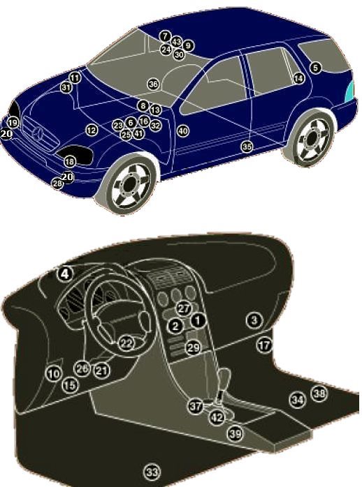
General layout of electronic components and control modules throughout the vehicle.
1. Air conditioning control unit – behind the audio system unit (up to 08/2001);
2. Automatic climate control ECU – integrated into the HVAC control panel (from 09/2001);
3. HVAC blower motor resistor – adjacent to the blower motor;
4. Solar / sunlight sensor (climate control system);
5. Antenna module – tailgate / rear door;
6. Anti-theft alarm system control unit (integrated into the multifunction control module);
7. Vehicle inclination / tilt sensor (anti-theft system, integrated into trip computer);
8. Anti-theft alarm system siren / horn – engine compartment;
9. Ultrasonic interior motion sensor (anti-theft system, integrated into trip computer);
10. Audio output amplifier (if equipped) – behind the left side of the instrument panel;
11. Battery;
12. Brake booster vacuum pump – left side of the engine compartment;
13. Brake booster vacuum pump control module – left side of the engine compartment;
14. Compass control module (navigation system) – under trim panel near tailgate latch;
15. Diagnostic link connector (DLC / OBD-II);
16. Fuse and relay box, engine compartment;
17. Fuse and relay box, passenger footwell;
18. Left headlamp control unit (models with Xenon headlights);
19. Right headlamp control unit (models with Xenon headlights);
20. Horns – behind the front bumper;
21. Immobilizer control module – attached to multifunction control module 2 (from 12/1999);
22. Immobilizer transponder ring antenna – on the ignition switch cylinder;
23. Turn signal / hazard flasher relay – integrated into multifunction control module 1;
24. Sunlight sensor – top center of the windshield;
25. Multifunction control module 1 – attached to the engine compartment fuse/relay box (functions: interior lighting, exterior lighting, horns, windshield wipers, A/C system pressure control, central locking, power windows, turn signals, anti-theft alarm, power sunroof, seat heaters, engine immobilizer; up to 11/1999);
26. Multifunction control module 2 – (functions: central locking, headlamp washers, heated rear window, seat heaters, A/C condenser fan motor, interior lighting);
27. Navigation system control unit (integrated into audio system, if equipped);
28. Ambient outside temperature sensor;
29. Parktronic / parking assist control module – behind the center switch panel;
30. Rain sensor – top center of the windshield;
31. Auxiliary fuse 1 – adjacent to the battery;
32. Auxiliary fuse 2 (FL7.5/10A), engine management – located in engine compartment fuse box (diesel models);
33. Power seat control module with memory, front left – under seat;
34. Power seat control module with memory, front right – under seat;
35. Left side impact sensor – lower B-pillar / center pillar (from 09/2001);
36. Right side impact sensor – lower B-pillar / center pillar (from 09/2001);
37. SRS / airbag control module;
38. Cellular phone interface control module – under front seat;
39. Transfer case control module (TCM);
40. Transfer case shift motor – mounted on the transfer case;
41. Electronic transmission control module (ETC / TCU);
42. Gearshift control module – automatic transmission selector lever assembly;
43. Trip computer / multi-information display.
