Mercedes-Benz Sprinter is a family of light-duty vehicles. The first generation was produced in Germany from 1995 to 2006 instead of the TN model, then until 2011 the cars were produced in Argentina. In this article, we will take a detailed look at the fuse box diagrams for the Mercedes Sprinter (1st Gen; body series - W901 / W902 / W903 / W904 / W905) 1995, 1996, 1997, 1997, 1998, 1999, 2000, 2001, 2002, 2003, 2004, 2005 years of manufacture.
Here you will find the locations and photos of distribution boxes. The fuses responsible for the “Cigarette lighter” and “Fuel Pump” are highlighted in bold.
In the passenger compartment
There are two distribution boxes here that are responsible for protecting the electrical circuits.
Fuse box #1 (main)

The main distribution box is located at the bottom of the steering column behind a plastic cover.
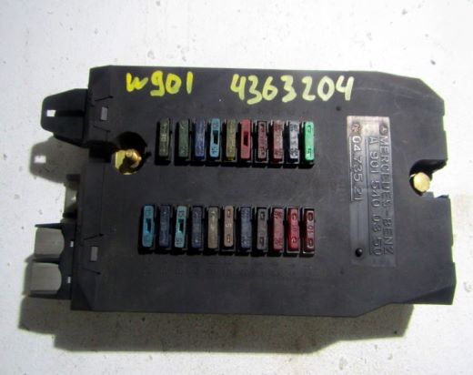
The photo shows an example.
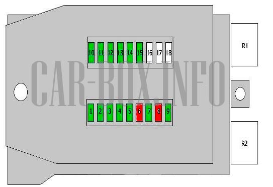
| Diagram (Sprinter models up to 2000 release) | ||
|---|---|---|
|
||
| No. | A | Decryption |
| 1 | 15 | Right parking light, right tail light |
| 2 | 15 | High beam, right headlight |
| 3 | 15 | Left headlight high beam, high beam indicator light |
| 4 | 15 | Back-up lamps |
| 5 | 15 | Stop lamps |
| 6 | 20 | Wiper motor |
| 7 | 15 | Horn (beep), rear window heater, accessory relay (circuit 15) |
| 8 | 20 | Interior light, cigarette lighter fuse, radio (circuit 30) |
| 9 | 15 | Clock, emergency warning light, parking light |
| 10 | 15 | Instrument panel illumination, license plate illumination lamp, daytime driving light |
| 11 | 15 | Left parking light, left tail light |
| 12 | 15 | Dipped beam, right headlight |
| 30 | 15 | Left headlight dipped beam |
| 14 | 15 | Fog lights, rear fog light |
| 15 | 15 | Radio receiver (circuit 15) |
| 16-18 | - | Backup for special equipment items |
| Purpose of relay modules | ||
| R1 | wiper relay | |
| R2 | Direction indicators | |
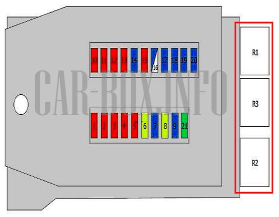
In 2000, the car went through a restyling.
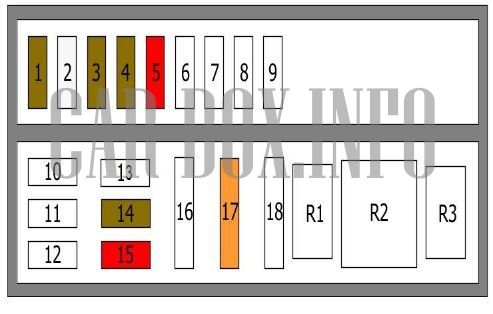
| Fuse location in the main fuse box (models from 2000 model year) | ||
|---|---|---|
|
||
| No. | A | Description |
| 1 | 10 | Right parking light, right tail light |
| 2 | 10 | High beam, right headlight |
| 3 | 10 | Left headlight high beam, high beam indicator light |
| 4 | 10 | Back-up lamps |
| 5 | 10 | Stop lamps |
| 6 | 20 | Wiper motor |
| 7 | 15 | Horn (beep), rear window heater, accessory relay (circuit 15) |
| 8 | 20 | Interior lighting lamp, cigarette lighter; radio (circuit 30) |
| 9 | 15 | Clock, emergency warning light, parking light |
| 10 | 10 | Instrument panel illumination, license plate illumination lamp, daytime driving light |
| 11 | 10 | Left parking light, left tail light |
| 12 | 10 | Dipped beam, right headlight |
| 13 | 10 | Left headlight dipped beam |
| 14 | 15 | Fog lights, rear fog light |
| 15 | 10 | Radio receiver (circuit 15) |
| 16 | 25 | Diesel engine control unit (circuit 30) |
| 17 | 15 | Engine control unit (circuit 30) |
| 18 | 15 | Ignition (circuit 15) |
| 19 | 15 | Mercedes Sprinter fuel pump fuse (circuit 30) |
| 20 | 15 | Heating system control panel (circuit 30) |
| 21 | 30 | Heating fan, front (circuit 30) |
| Purpose of relay modules | ||
| R1 | Wipers | |
| R2 | Direction indicators | |
| R3 | Engine management | |
Fuse box #2
The heating fan fuse is located in the fuse box under the driver's seat. In vehicles with optional equipment, other fuses and relays are also located in the fuse box. Their location depends on the vehicle equipment.
| Diagram | ||
|---|---|---|
|
||
| R1 | Horn (beep) relay | |
| R2 | Special equipment | |
| R3 | Coolant pump relay | |
| # | Fuses | A |
| 1 | Instrument combination | 7.5 |
| 2 | Additional heater | 25 |
| 3 | Buzzer | 7.5 |
| 4 | Buzzer | 7.5 |
| 5 | Additional heater | 10 |
